


 572 / 1232

Automated Manual Transmission
44
Hydraulic Speed Selection Hydraulic Actua-
tor Unit and Clutch Fitment:
1. Check that the gear engagement actuator
is in “neutral” position as shown in the
figure.
Suitably grease the gear selection actuator
dog.
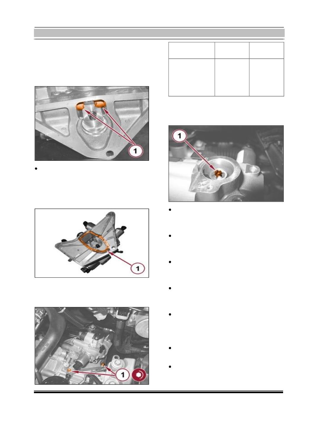
1. Apply a bead of silicone sealant to the hy-
draulic unit in the area shown in the
figure.
1. Place the hydraulic unit in its housing and
tighten the front screws and the rear
screw to the prescribed torque.
Component
Fixing Dia
Value (Nm)
Hydraulic gear
activation unit
Screw M8
23 – 28
1. Rotate the gear selection actuator 90°
clockwise in order to bring it to the posi-
tion indicated in the figure.
Place the gear selection actuator cover in
its housing and tighten the appropriate
screw.
Connect the pipe from electric pump to
hydraulic unit, hydraulic unit side, and
tighten the relevant connector.
Connect the pipe from hydraulic unit to
clutch release actuator complete with new
O-rings and engage the retaining clip.
Connect the pipe from hydraulic unit to
reservoir, hydraulic unit side, and tighten
the relevant band.
Connect the wiring for manual gearbox hy-
draulic selection system on hydraulic
selection system on hydraulic selection
unit.
Assemble the protection/ guard under the
engine.
Refill the electro-hydraulic selection gear-
box hydraulic control system, with
reference to: