


 569 / 1232

Automated Manual Transmission
41
Hydraulic Unit/Electro hydraulic Selection
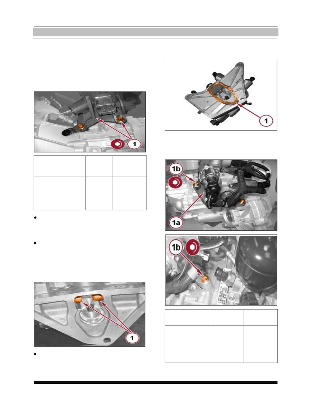
Gearbox Electric Pump Assembly with Gear-
box Removed Fitment:
1. Place the power unit back in its housing
and tighten the screws to the prescribed
torque.
Component
Fixing
Dia
Value (Nm)
Electro- hydraulic
selection gearbox
power unit
Screw
36 – 44
Place the solenoid valve unit complete with
new O-ring back in its housing and tighten
the relevant screws.
Place the gear selection dog back in its
housing and tighten the relevant screw.
1. Check that the gear engagement actuator
is in “neutral” position as shown in the
figure.
Suitably grease the gear selection actuator
dog.
1. Apply a bead of silicone sealant to the hy-
draulic unit in the area shown in the fig-
ure.
1. Place the solenoid valve unit (1a) back in
its housing and tighten the screws (1b) to
the prescribed torque.
Component
Fixing Dia
Value (Nm)
Hydraulic gear
activation unit
Screw M8
23 – 28
1. Rotate the gear selection actuator 90°
clockwise in order to bring it to the posi-