


 515 / 1232

DRIVETRAIN C549
40
NOTE
: 0.12
corresponds to the recommended
interference for the bedding in and pre-loading
of the differential bearings.
4. After determining the exact value of the size
of the shim, try to get as close as possible to
this value using the shims supplied as spares.
If there are no shims available that
correspond exactly to the value produced in
this way, fit the shim(s) immediately larger.
5. Place the differential bearing pre-loading shim
(s) in position.
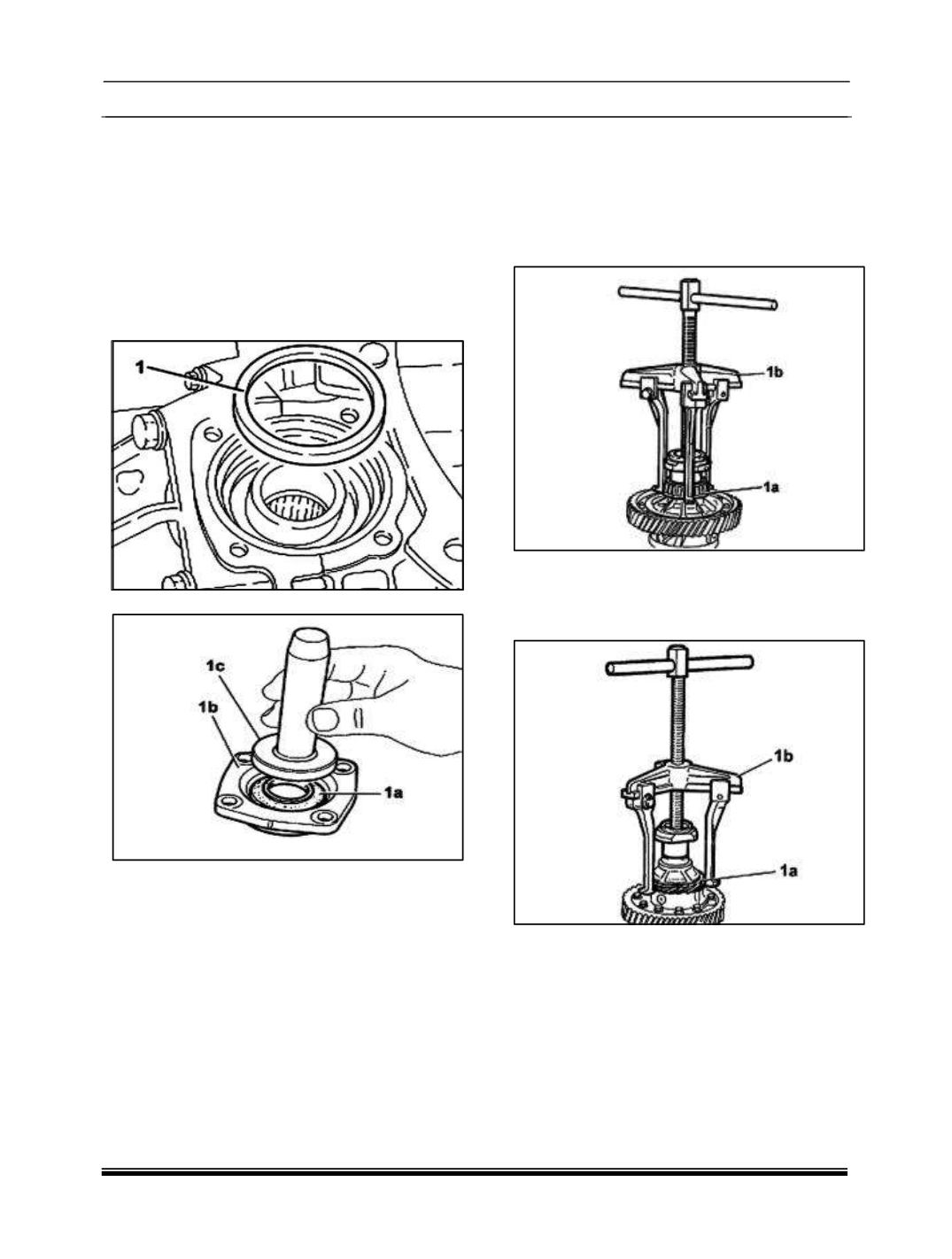
6. Fit a new oil seal (1a) on the differential flange
7. (1b) using the
tool (1c)
287458902611
(Fitting tool) .
Fit the differential flange and
secure it tightening the bolts to torque.
8. Fit the left differential inner driveshaft.
9. Fit the gear selection/engagement mounting
bracket and secure it using the bolts.
10. Unscrew the fastenings and remove the
TRANSAXLE and differential from the support
tool
287058900607
(TRANSAXLE Support).
11. Remove the support tool from the overhaul
stand and put it down.
12. Refit the TRANSAXLE assembly on vehicle
using suitable transaxle support bracket.
4.1.2.5. DIFFERENTIAL ASSEMBLY –
OVERHAUL
1. Remove the bearings (1a) from the differential
internal casing using the tools (1b)
287458902619 (Extractor), (1c) 28745890
2620
(Extractor
arms)
and
(1d)
287458902621 (Fitting Tool).
2. Remove the speedometer idler drive gear (1a)
using the tools (1b) 287458902619
(extractor), (1c) 287458902620 (Extractor)
and (1d) 287458902621 (Fitting tool).
3. Mark the position of the ring gear and
differential internal casing.