


 106 / 561

AMT KIT
26
G. POWER UNIT (PWU) BASE PLATE
REMOVAL AND RE-FITMENT ON BENCH: -
Removal:
Disconnect all the connectors of the system
wiring harness (DC Motor, Cultch Position
Sensor and Transmission Control Unit) and
remove the ‘Plastic Clip’ pulling it out from its
threaded hole on the ‘Power Unit Base Plate’
body.
Remove the ‘Mechatronic Gear Actuator’ unit
(MGA) first (refer the procedure. Mechatronic
Gear Actuator Unit (MGA) Removal and Re-
Fitment on Bench).
Installation:
Assemble the ‘Power Unit Base Plate’ on the
fixture.
In order to guarantee right ‘Mechatronic Gear
Actuator’ translation during the mounting, to
avoid O-rings damages, screw three rods
φ6x100 mm length, with 15 mm threaded M6,
in the ‘Power Unit Base Plate’ holes used by
‘Mechatronic Gear Actuator’ fixing screws.
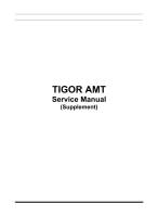
Assemble the O-rings on the connectors.
Mount the connectors with O-rings in their
seats on ‘Power Unit Base Plate’, after
lubrication with new ‘CS Speed’ oil also
lubricate the ‘Mechatronic Gear Actuator’
seats.
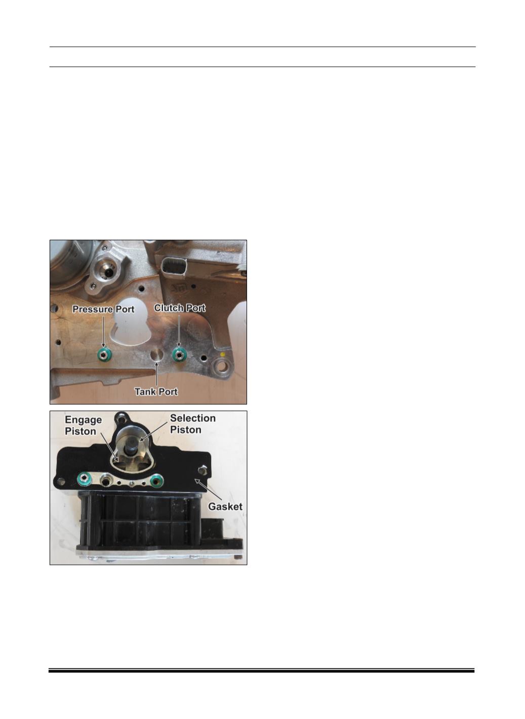
Remove traces of oil from the ‘Mechatronic
Gear Actuator’ seal surface in contact with
gasket with care to avoid contamination from
foreign materials (dust, metal burrs, etc.) or
surface damages.
Assemble the gasket on the ‘Mechatronic
Gear Actuator’ with the correct orientation,
inserting the centering pins into the fixing
holes of the ‘Mechatronic Gear Actuator’
body.
Position the ‘Mechatronic Gear Actuator’ with
gasket over the ‘Power Unit Base Plate’ using
the threaded rods for reference and moving it
parallel towards the mating surface.
When the ‘Mechatronic Gear Actuator’ body
seats came in contact with O-rings, push it
slowly, with appropriate load to complete the
assembly.
Unscrew the rods and screw the three screws
for fixing the ‘Mechatronic Gear Actuator’ on
‘Power Unit Base Plate’ at the right torque 10
± 1 Nm.
Connect the connectors of the wiring harness
on the ‘Transmission Control Unit’ and ‘Cultch
Position Sensor’.
Insert the plastic clip into its threaded hole on
the ‘Power Unit Base Plate’ body and connect
the connector of wiring harness on the DC
Motor.
Fill the ‘Oil Tank’ with new ‘CS Speed’ oil, at
the Max. Level “@ 0 bar” (no pressure in the
hydraulic circuit) and restore it after the purge
procedure.
Screw the ‘Oil
Tank Cap’ at the right torque.