


 105 / 561

AMT KIT
25
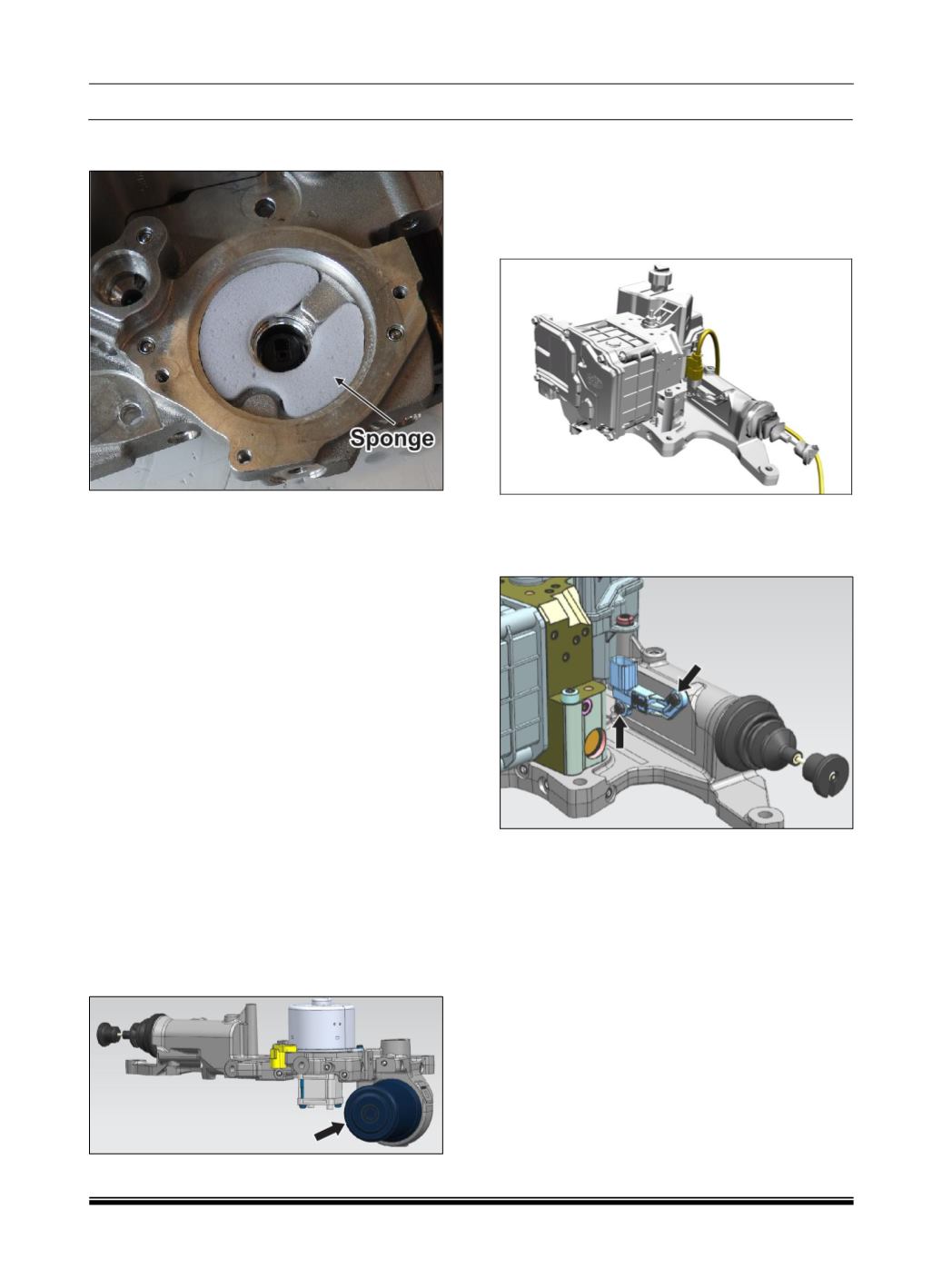
Insert the ‘Sponge’ in the ‘Power Unit Base
Plate’ seat.
Align the ‘Dc Motor’ on the ‘Power Unit Base
Plate’ and insert its axe in the ‘Oldham Joint’
slot, continue the translation of the ball
bearing in its ‘Power Unit Base Plate’ seat
with care.
Preassemble the two screws M5x15 in the
motor flange at 180° before and after the
third screw M5x15 (the ground screw)
without tighten.
Then screw with alternating sequence the
two screws at 180° until to reach the right
torque (6 ± 1 [Nm]) and then tighten the
ground screw with the same torque.
Connect the connector of the wiring harness
on the ‘Dc Motor’.
Install ‘Oil Tank’ (refer the procedure Oil
Tank Removal and Re-Fitment on Bench).
E. HYDRAULIC
OIL
ACCUMLATOR
REMOVAL AND RE-FITMENT:
DANGER!!
Do not remove hydraulic oil accumulator, it is
pressurized unit it can pose a safety threat.
F. CLUTCH POSITION SENSOR REMOVAL
AND RE-FITMENT:
Removal:
Disconnect the connector of the wiring
harness from the ‘Clutch Position Sensor’.
Unscrew and remove the two screws fixing
the ‘Clutch Position Sensor’ on the ‘Power
Unit Base Plate’ body.
Installation:
Position the ‘Clutch Position Sensor’ on its
seat using the two screws at the right torque
2.5 ± 0.1 Nm.
Connect the connector of the wiring harness
on the ‘Clutch Position Sensor’.