


 1668 / 1906

SUPPLEMENTARY RESTRAINT SYSTEM (SRS)
20
ON VEHICLE REPAIR
REMOVAL
1. Disconnect the battery connection.
2. Remove lower “B” pillar trim.
(For procedure refer
“B” pillar trim removal procedure in CAB section.)
3. Disconnect the electrical connection from side
impact sensor.
4. Loosen and remove the mounting bolt and re-
move the side impact sensor from “B’ pillar.
FITMENT
For fitment follow reverse procedure of removal.
NOTE
The FIS and SIS are of same type in vehicle.
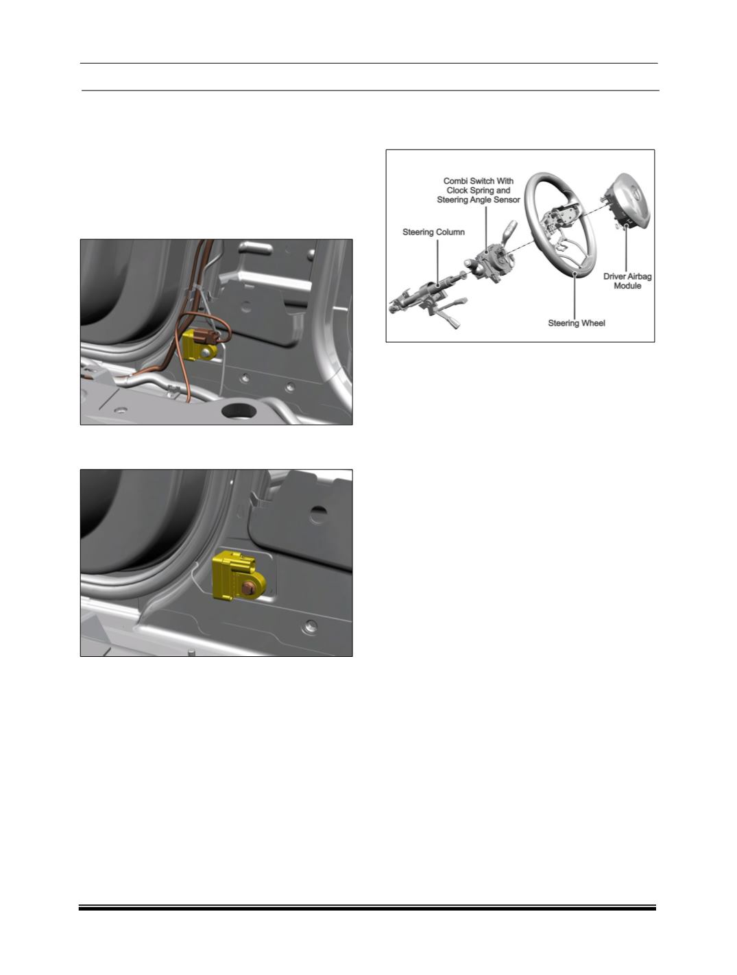
III AIR BAGS
DRIVER AIR BAG (DAB)
The driver airbag module is located in the steering
wheel and its function is controlled by the SRS ECU.
A bag within the module inflates to protect the driver
in the event of a collision severe enough to deploy
the system.
The driver airbag module connects to the steering
column wiring harness via a rotary coupler called as
clock spring. Within the driver airbag module is a
squib which, when given the correct current by the
SRS ECU, inflates the airbag by initiating a chemical
reaction. In deployment, the airbag inflates within a
fraction of a second and then deflate at a controlled
rate as the driver body regions; typically head and
chest interact with airbag. Vents in the airbag control
its deflation.
The SRS ECU regularly applies a test current to the
driver airbag squib to confirm continuity of the igni-
tion circuitry.