


 1596 / 1906

ELECTRICAL
294
REMOVAL:
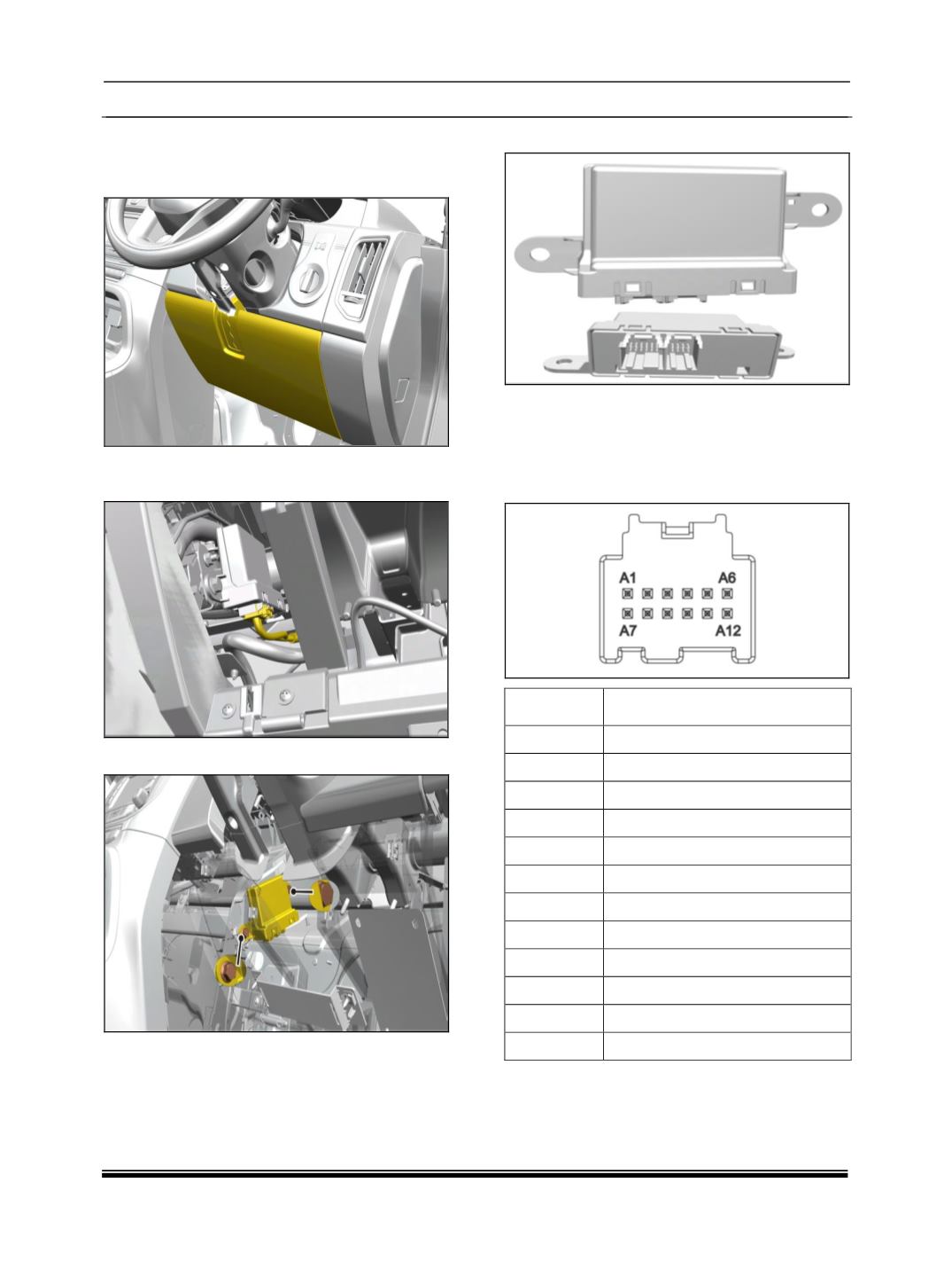
1. Remove the assembly cover steering column
lower rhd side
2.Disconnect wiring harness connector from the
cable assembly.
3.Remove two mounting bolts of controller.
4.Remove PCD controller.
REFITMENT
Follow the removal process in reverse.
PINOUT DETAILS
1.
Position A connector
PIN
DESCRIPTION
A1
FRONT PP ENABLE
A2
NC
A3
NC
A4
PP ENABLE LED
A5
REV. GEAR
A6
NC
A7
KL15
A8
NC
A9
CAN_H
A10
CAN_L
A11
NC
A12
GND
2. Position A connector