


 1408 / 1906

ELECTRICAL
106
4. Snap fit the assembly lower nacelle and
assembly upper nacelle, and fit the three
mounting screws in the assembly nacelle lower.
5. Snap fit the lower steering column cover.
6. Fit the steering wheel properly. (For procedure
refer steering section)
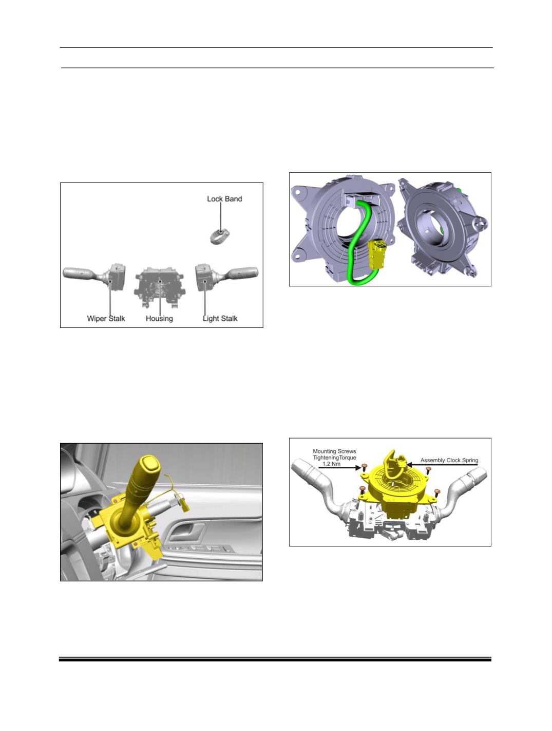
COMBI SWITCH STALK REPLACEMENT:
CHILD PARTS:
REMOVAL:
1. Pull out the lower steering column cover.
2. Remove the both assembly nacelle upper and
lower.
3. Disconnect the wiring harness connector from
the combi-switch stalk.
4. Remove two mounting screws of light stalk as
shown in below given figure.
5. Take out the defective stalk.
REFITMENT:
1. Align the new stalk in the combi-switch housing.
2. Fit the two mounting screws.
Tightening torque for screws – 0.06 Kgfm.
3. Connect the electrical connection to the switch.
4. Snap fit the assembly lower nacelle and
assembly upper nacelle, and tighten the three
mounting screws in the assembly nacelle lower.
5. Snap fit the lower steering column cover.
CLOCK SPRING:
REMOVAL:
1. Remove the steering wheel (For procedures
refer steering section).
2. Pull out the steering column lower cover.
3. Loosen three fixing screws of assy necelle
lower and assy necelle upper, located in
bottom side of assy nacelle lower.
4. Dismantle both necelle from snap fitting and
take out the both assy nacelle.
5. Remove four mounting screws of clock spring
and take out the clock spring.
REFITMENT:
For refitment follow the reverse procedure of
removal.