


 1209 / 1906

Anti-lock Braking System(ABS)
19
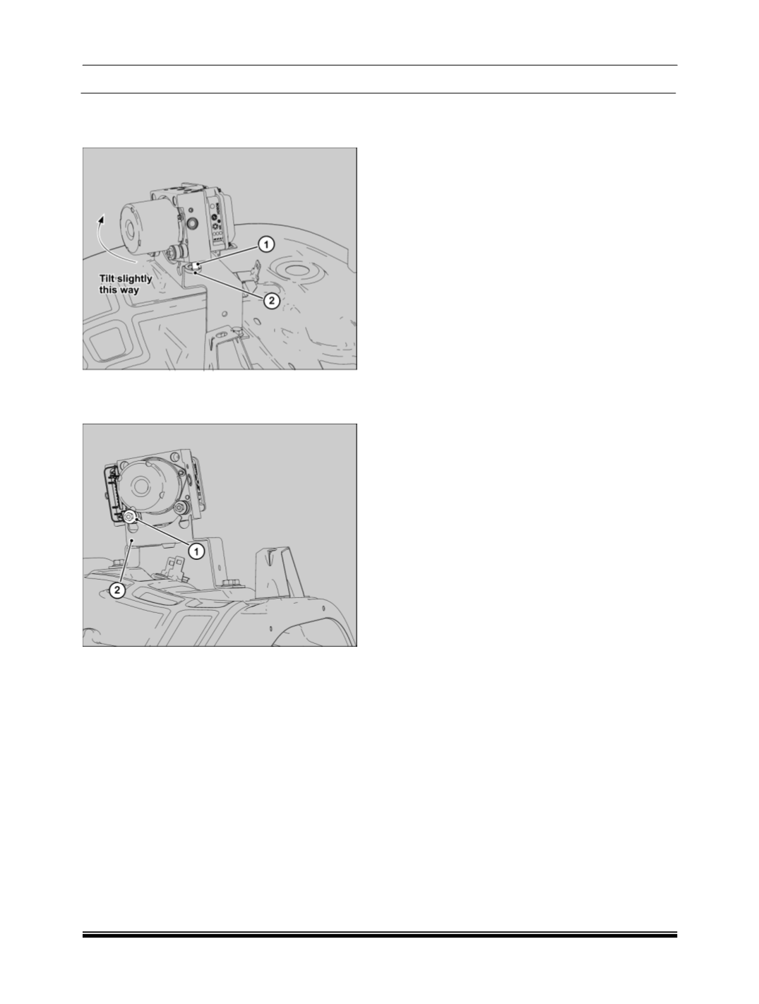
7. Slightly tilt the Unit forward
(towards firewall)
and release the centre pin (1) from the centre
damping element (2) on the mounting bracket.
8. Lift the Unit to release the left side
(when
viewed from front)
damping element (1) from
the mounting bracket (2).
NOTE:
ABS ECU and is not serviceable.
Refer ABS troubleshooting for faults related to
ABS ECU.
Installation :
1. Follow the reverse order of removal to install
the ECU on the mounting bracket i.e. :
a. Insert the left side damping element.
b. Slightly tilt forward and insert the centre
pin in centre damping element.
c. Insert the right side damping element.
d. Ensure that the ECU is seated properly
and tighten the holding nuts to a torque of
0.8 ± 0.2 Kg-m.
2. Reconnect the brake lines. Be certain that the
brake lines have been connected to the
correct ports to ensure proper ABS operation.
Tighten the coupling nut to specified torque.
(1.4 – 1.8 Kg-m)
3. Connect the ECU connector.
4. Bleed the brake system.
NOTE :
For brake bleeding procedure conventional/ using
diagnostic tool refer Brakes group.
5. Clear all faults using diagnostic tool.
6. Road test the vehicle to ensure proper
operation of the conventional brakes and ABS
system.