


 1036 / 1906

FRONT AXLE (4X4)
38
NOTE
Ensure that the removed motor is kept in oil /
water free environment and its connector are
suitably protected as well as “O” Ring.
Discard the bolts and use new bolts while
assembly.
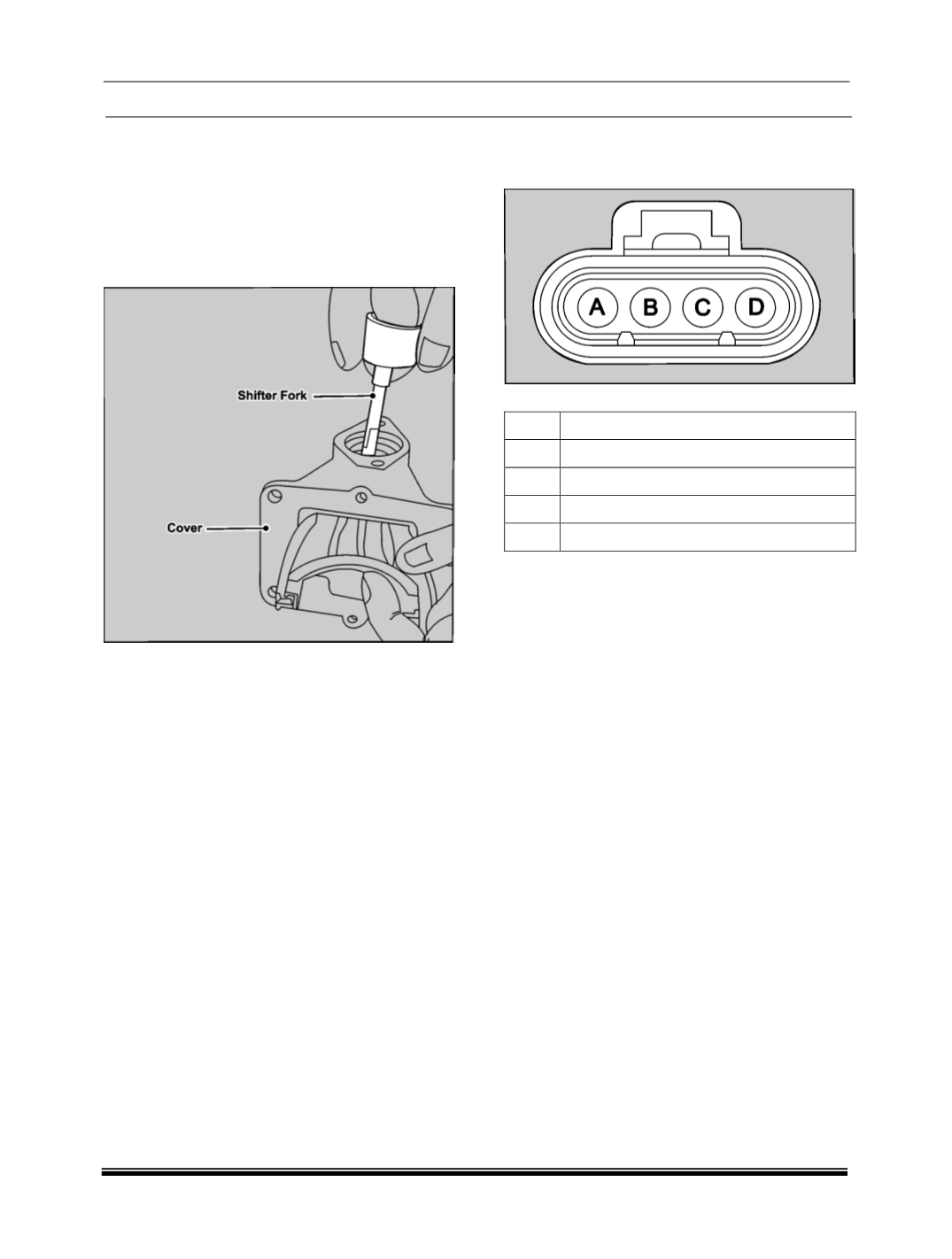
3. Carefully pull out shifter fork shaft from cover.
WARNING
The shaft is spring loaded in the cover assembly
so proper care should be taken while removing.
NOTE
Properly mark the shifter fork for its orientation
after its removal.
4. Separate the shift fork and spring from
disconnect cover.
INSPECTION
A. PHYSICAL CHECKING
1. Check for any physical damage to the FAD
actuator, if found damaged replace the same.
2. Check the wiring harness for any loose
contacts and cable damage, if found repair or
replace the same
.
3. Check for dust on the FAD if found clean the
same before assembly.
4. In case of water ingress, replace the FAD.
B. ELECTIRCAL CHECKING
CONNECTOR DETAILS
PIN DETAILS
PIN
DESCRIPTION
A
Front Axle Disconnect Actuator Signal
B
Ground
C
Front Axle Disconnect Feedback Signal
D
Power Supply
1. Switch ON the ignition and shift to 4x2 mode.
2. Switch OFF ignition, disconnect the connector
at the FAD actuator, Switch ON the ignition
then using voltmeter/multimeter measure the
voltages between
Pin B and Chassis ground: Measured voltage
= 0 Volts
Pin D and Chassis ground: Measured voltage
= Battery voltage (8 to 12 V)
Pin A and Chassis ground: Measured voltage
= 4 to Battery voltage.
Pin C and Chassis ground: Measured voltage
= 0 to 0.9 V.
If the voltage is out of the above mentioned range,
check for any short circuits or open circuits.
Reconnect the connector after rectifying the
problem