


 1016 / 1906

FRONT AXLE (4X4)
18
C. TONER RING
REMOVAL
1. Remove the stone guard.
(For procedure refer
stone guard removal in body section.)
2. Remove front wheels.
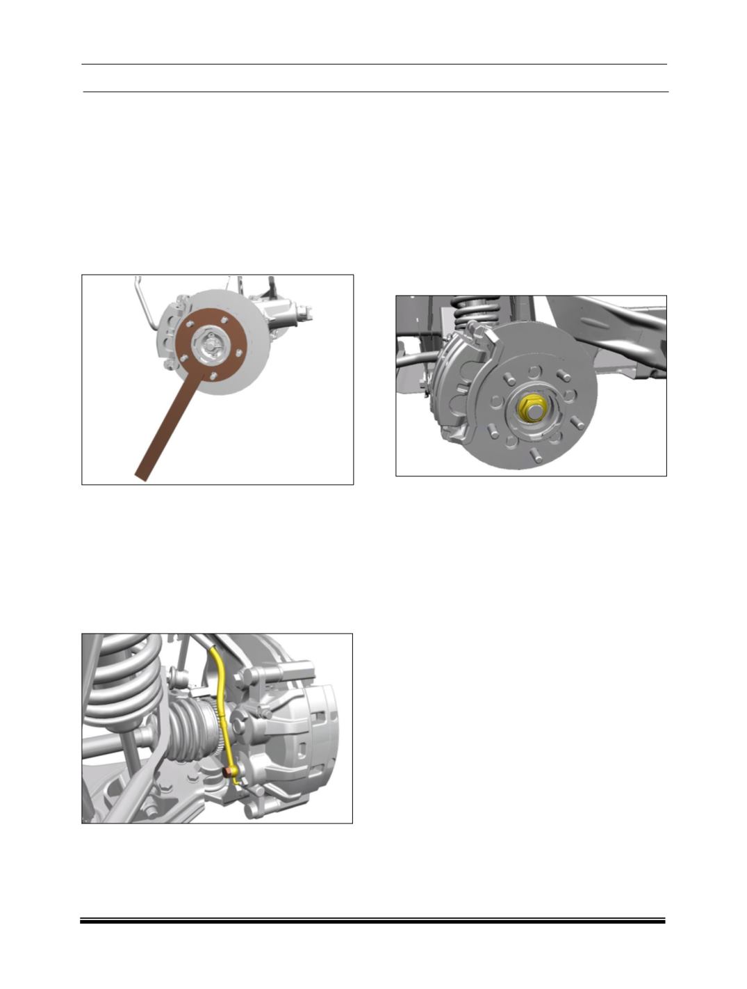
3. Remove split pin and hold the hub assembly
with the hub holder
(Part No. 287058903316)
.
Secure the hub holder tool on the hub
assembly by locking with nuts and loosen drive
shaft nut.
4. Lift the vehicle in two post lift.
5. Loosen and remove mounting bolts of front
brake caliper assembly with carrier and
remove the brake caliper assembly. (
For
procedure refer Brakes section
).
NOTE
Don’t remove hydraulic brake line connected to
Brake caliper assembly.
6. Disconnect steering rack and pinion OBJ end
from stub axle. (
For procedure refer Steering
RAP removal section
)
7. Remove front wheel speed sensor (
For
procedure refer Brakes - ABS section
) and
disconnect the bracket by removing the
mounting bolt which is for brake hose from the
stub axle assembly.
8. Loosen and remove the mounting nut of ARB
(Anti roll bar)
link assembly from stub axle.
9. Remove the drive shaft nut which was loosen
earlier.
10.Disconnect upper wishbone ball joint
. (For
procedure refer suspension upper wishbone
ball joint removal section)
11.Support the stub axle assembly from below.
Disconnect lower wishbone ball joint using
puller
(Part No. 287058904601)
.
(For
procedure refer suspension lower wishbone
ball joint removal section.)