


 96 / 1526

57
4 DLT ENGINE
M
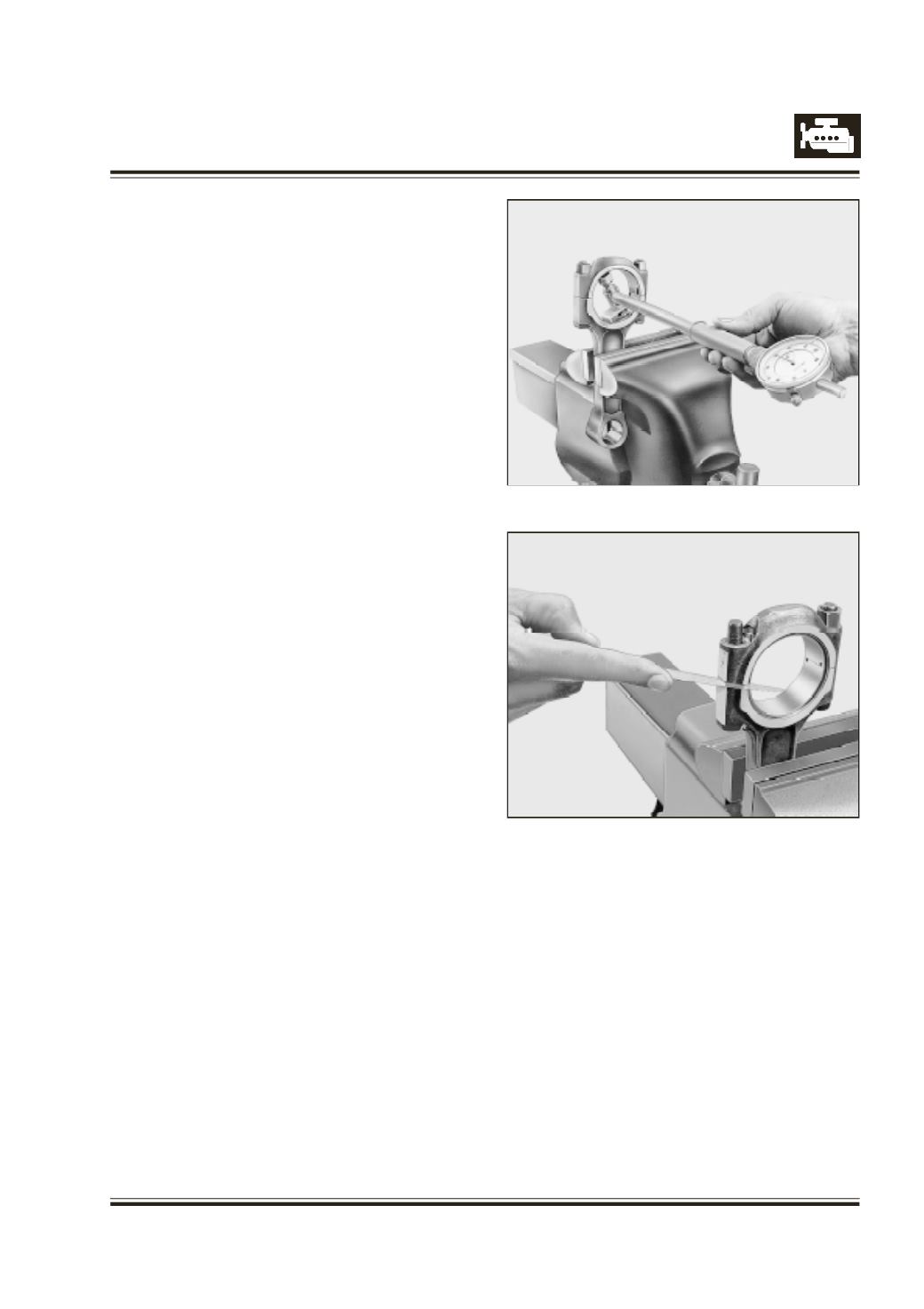
easure connecting rod bearing bore.
Refer Figure 101
IF CONNECTING ROD BIG END PARENT BORE
DIMENSION IS MAINTAINED WITHIN SPECIFIED
LIMITS, PROPER BEARING BORE DIMENSION IS
AUTOMATICALLY ACHIEVED.
H
owever it must be physically measured and
confirmed. Measure pretension of connecting rod
bearing shell with feeler gauge after loosening
connecting rod bearing cap mounting nut on opposite
side of bearing shell lug. Refer Figure 102
CONNECTING ROD BEARING SHELL ARE
PRECISION FINISHED AND SHOULD NOT BE
BORED OR SCRAPED.
INSPECTION OF INJECTION NOZZLE
Checking nozzle opening pressure
- Connect injector assembly to nozzle tester.
- Slowly depress nozzle tester lever and read pressure
gauge when nozzle starts opening.
- If opening pressure is not as per specified value,
then adjust as required by selecting proper shims.
Check nozzle for leakage
- Slowly depress nozzle tester lever until pressure
gauge shows 125 bar.The nozzle is leak proof, if no
drop comes out of nozzle tip within 10 seconds.
- Rectify the leak by cleaning the nozzle elements.
R
eplace nozzle if necessary.
Checking nozzle spray
- Close shut-off valve.
- Depress nozzle tester lever 4 -5 times. The nozzle
will then buzz very softly. The automization is
satisfactory when the jet cone has uniform closed
contour and is finely automized.
Inspection of glow plugs
- Check glow plugs for short circuits and or for burning.
Replace them if necessary.
WATER PUMP
C
heck water pump for free rotation. Check for water
leakage through leakage hole. It indicates that water
seal is damaged and leaking. Replace the water pump
if necessary.
Dismantling and repairing of water pump is not
recommended.
Fig. 101
Fig. 102
Checking of thermostat element
1. Remove thermostat element from thermostat
housing.
2. Mount thermostat element in suitable fixture and
place the fixture in a vessel filled with water.
3. Fix dial gauge with its spindle on valve surface with
a pretension of 0.5 mm.