


 93 / 1526

54
4 DLT ENGINE
I
f run out exceeds permissible limits, straighten crank
shaft in cold condition on press carefully.
S
imilarly check lateral and radial run outs of flywheel
mounting flange.
C
heck crank shaft main bearing and crank pin
journal dimension.
I
f necessary, grind crank shaft main bearing and
crank pin journal to next under size.
MAINTAIN CORRECT FILLET RADII FOR
JOURNALS.
C
aremust be taken during grinding to ensure that width
of journals is not increased.
S
hould it be necessary to grind sides of 4th main
bearing journals, grind it to next over size.
R
e-chamfer oil holes on journals to avoid scoring of
new bearing shells.
F
inish journals by lapping them with 320 grit lapping
cloth of suitable width.
A
fter grinding recheck main bearing and crank pin
journal dimensions.
A
lso recheck run out of crank shaft.
T
horoughly clean crank shaft with kerosene. Use
wire brush for cleaning oil holes.
IT IS ADVISABLE TO RECHECK CRANK SHAFT
FOR CRACKS AND BALANCE AFTER GRINDING.
A
pply grease to all machined surface, if crank shaft
is to be stored. Crank shaft must always be stored
in vertical position.
CAM SHAFT
C
arry out visual inspection of cam shaft for:
- Over heating of journals, which is indicated by
bluish/brown colour.
- Deep scoring marks on journals and cam lobes
- Cracks, which should be checked on a magnetic
crack detector.
C
heck hardness of cam shaft journals and cam
lobes.
It should be 48-54 HRC.
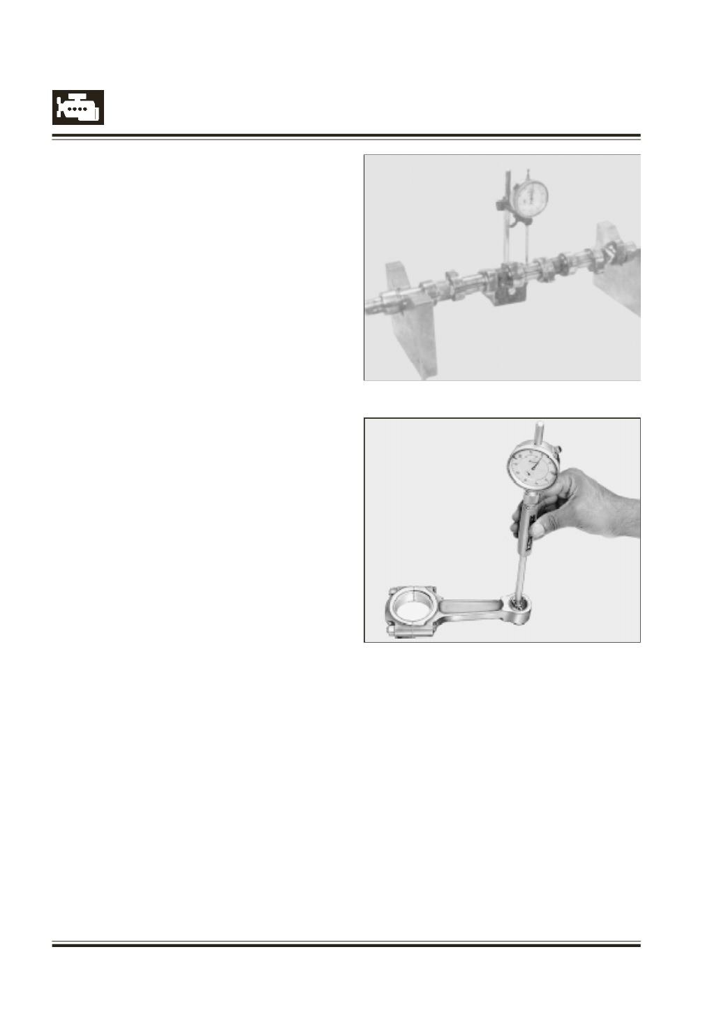
C
heck cam shaft run out at 2nd, 3rd and 4th journal
by supporting it onV-block at 1st and 5th journal.Refer
Figure 93
CONNECTINGRODS
I
nspect connecting rod small end bush and if
necessary remove it.
C
heck connecting rod small end parent bore
dimension. Refer Figure 94
I
f necessary machine Connecting rod small end parent
bore to next over size.
ENSURE THAT CONNECTING ROD BIG END AND
SMALL END AXES ARE PARALLEL TO EACH
OTHER WITHIN SPECIFIED LIMITS
Fig. 93
Fig. 94