


 94 / 1526

55
4 DLT ENGINE
O
il parent bore in connecting rod.
I
nstall new bush in such a way that slit is positioned
at approximately 45
0
from vertical axis.
D
rill oil hole in new bush.
F
inish connecting rod small end bush bore on a
connecting rod boring machine. Alternately
connecting rod small end bush may be reamed.
I
nstall connecting rod bearing caps without bearing
shells on connecting rod.
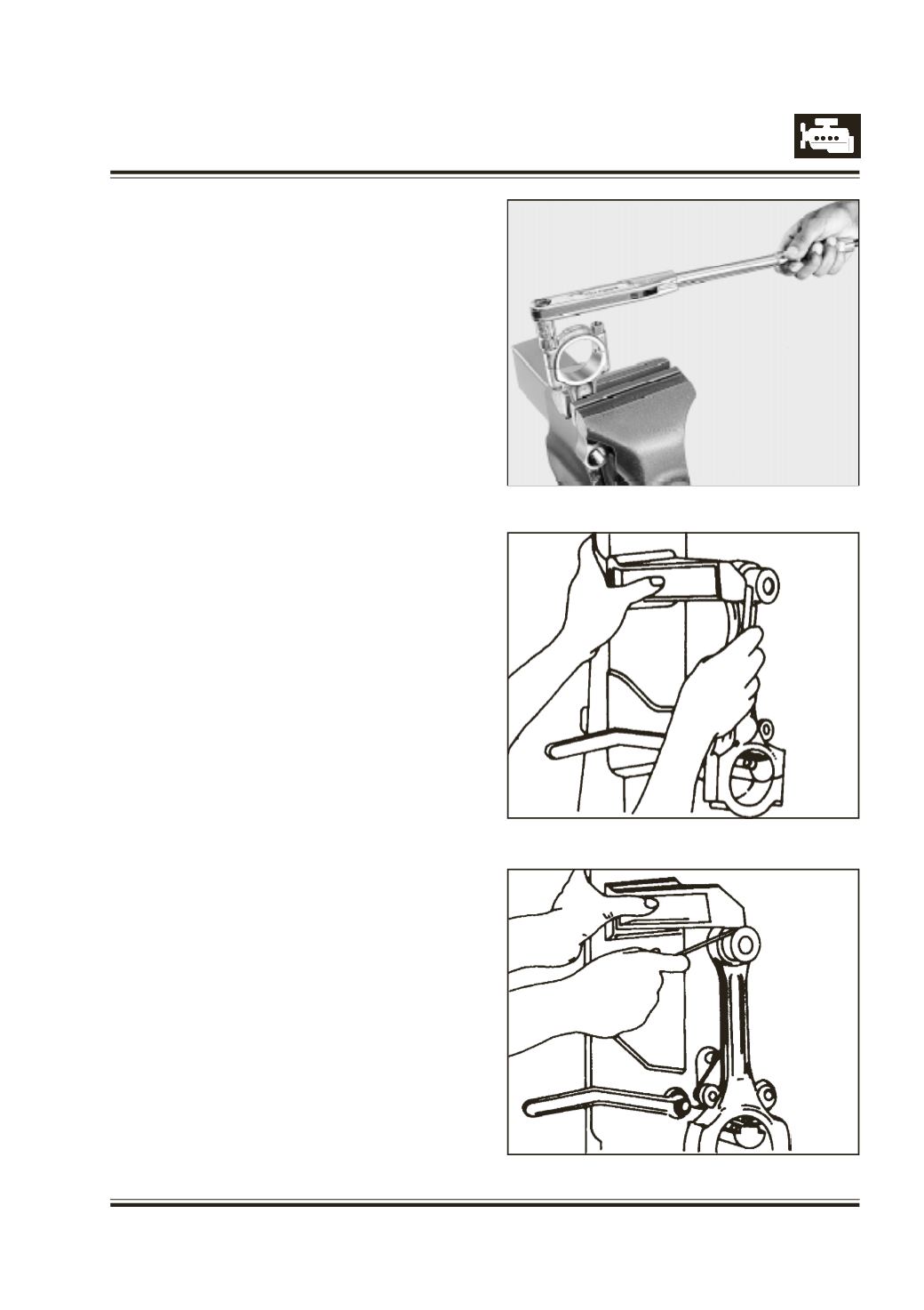
T
ighten connecting rod bearing cap mounting nuts
to specified torque. Refer Figure 95.
ENSURE THAT IDENTIFICATION NUMBERS FOR
CONNECTING ROD AND CONNECTING ROD
BEARING CAP ARE MATCHED AND NOTCHES
FOR BEARING SHELLS ARE ON SAME SIDE.
C
heck twist and bend of connecting rod by using
new piston pin in connecting rod small end bush.
Refer Figures 96 & 97
M
easure twist and bend of connecting rod with feeler
gauge with respect to vertical face of connecting
rod alignment gauge in vertical and horizontal plane
at a distance of 50 mm from line joining centers of
connecting rod small end and big end bosses.
I
f necessary, straighten connecting rod in cold
condition. Since a slight clearance exists between
connecting rod bolts and corresponding connecting
rod bearing cap holes, it is possible that connecting
rod bearing cap once removed may be installed off
center, by which dimension of connecting rod big
end parent bore will be different in different direction.
If there is a difference noticed in connecting rod big
end parent bore dimension, connecting rod bearing
cap can be centralized by lightly tapping it with mallet
in required direction after slightly loosening
connecting rod bearing cap mounting nuts.
Fig. 95
Fig. 96
Fig. 97