


 905 / 1526

49
ENGINE2.2LDICOR
l
Install piston rings in their respective position on
piston using ring expander (Fig. 107).
l
Stagger piston rings gaps such that they are 120°
apart (with butt gap not in line with piston pin)
Fig. 107
CRANKSHAFT
Clean and carry out visual inspection of crank shaft for
Following
l
Overheating of journals, which is indicated by
bluish brown colour
l
Scoring marks on journals
l
Cracks, which should be checked on magnetic
crack detector
l
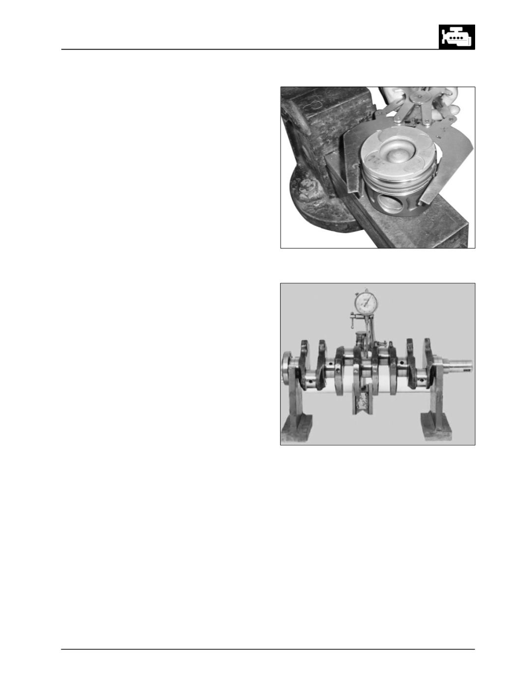
Check crank shaft run out by supporting it on V-
block at 1st and 5th main bearing journals (Fig.
108)
l
If run out exceeds permissible limits, straighten
crank shaft in cold condition on press carefully.
l
Similarly check lateral and radial run outs of
flywheel mounting flange.
l
Check crank shaft main bearing and crank pin
journal dimension.
l
Record the readings in the format given at the end
of this group. (Engine Inspection Sheets).
If necessary, grind crank shaft main bearing and crank
pin journals to next under-size.
MAINTAINCORRECTFILLETRADIUSFORJOURNALS
l
Care must be taken during grinding to ensure that
width of journals is not increased.
l
Should it be necessary to grind sides of 4th main
bearing journal, grind it to next under size.
l
Re-chamfer oil holes on journals to avoid scoring
of new bearing shells.
Fig. 108