


 902 / 1526

46
ENGINE2.2LDICOR
Fig. 98
l
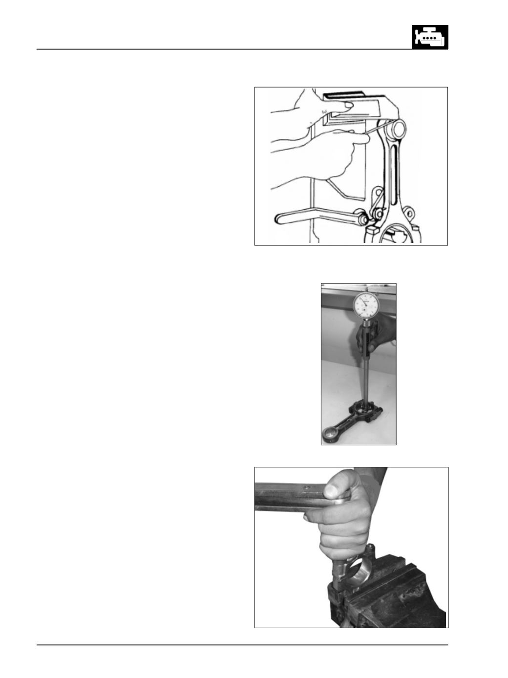
If necessary, straighten connecting rod in cold
condition. Since a slight clearance exists between
connecting rod bolts and corresponding
connecting rod bearing cap holes, it is possible
that connecting rod bearing cap once removed
may be installed off center, by which dimension
of connecting rod big end parent bore will be
different in different directions. If there is a
difference noticed in connecting rod big end
parent bore dimension, connecting rod bearing
cap can be centralized by lightly tapping it with
mallet in required direction after slightly loosening
connecting rod bearing cap mounting nuts.
l
If one or more connecting rods are to be replaced,
ensure that difference in weight of connecting rod
in one engine is within permissible limits.
l
Install new pair of connecting rod bearing shell
according to size of crank pin journal diameter,
making sure that securing lugs of bearing shells
are properly seated in grooves of connecting rod
and its bearing cap.
NOTE
Lower and upper bearings are different and to be
fitted properly.
l
Install connecting rod bearing cap with bearing
shell on connecting rod. Tighten connecting rod
bearing cap mtg. nuts to specified torque
(Fig.100)
Fig. 99
Fig. 100
l
Check connecting rod big end parent bore
dimension. (Fig. 99)
l
If connecting rod big end parent bore is slightly
more than maximum permissible limits, it is
possible to reclaim connecting rod provided the
wear is confined only to connecting rod bearing
cap. Connecting rod bearing cap mating surface
may be slightly faced. Parent bore should then be
finished on a connecting rod boring machine.
l
ENSURETHATCONNECTINGRODBIGENDAND
SMALLENDAXESAREPARALLELTOEACHOTHER
WITHINSPECIFIEDLIMITS.CENTRETOCENTRE
DISTANCEBETWEENCONNECTINGRODSMALLEND
ANDBIGENDISMAINTAINEDWITHINSPECIFIED
LIMITS.