


 392 / 1526

16
FRONT AXLE - 4
X
4
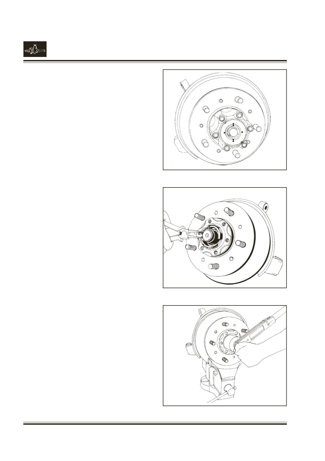
Remove hub - lock assembly.
Note :
1. The knob should be at lock position.
Fig.10
Note :
2. Hub - lock assembly is a non - serviceable
component. If it is established that problem is
in hub - lock, it is to be replaced with a new
one.
Remove snap ring from axle shaft.
Fig. 11
Remove washer and outer, inner brake assembly.
(Hub - lock components)
Remove axle shaft.
Using a socket, spanner pt. no. 2704 5890 3318
remove the outer spindle lock nut, lock ring, and inner
wheel bearing adjusting nut.
Fig. 12
Note :
The inner adjusting nut has a pin assembled,
to which engages the lock ring. Be careful that
the pin is not damaged. Replace nut, if
necessary.
Remove spindle assembly by pulling steering knuckle
from the hub.
Fig. 10
Fig. 11
Fig. 12
AUTO
LOCK
AUTO
LOCK