


 267 / 1526

26
GEAR BOX G-76
DIS-ASSEMBLY
DIS-ASSEMBLY OF DRIVE SHAFT
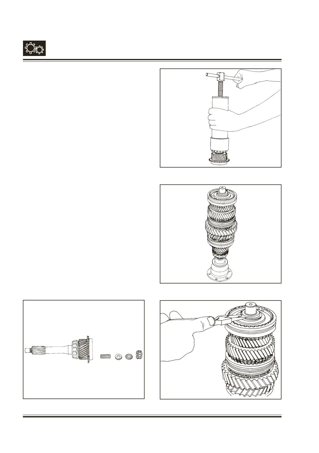
Refer Fig. 28
Remove synchro cone (17)
Remove needle roller bearing (7)
Remove thrust bearing (6), spacer (5) and
compression spring (4).
Remove taper roller bearing inner race (11) with the
help of puller
Pt.No. 2654 5890 26 12.
Fig. 29
DIS-ASSEMBLY OF MAIN SHAFT
Hold the main shaft assembly (46) such that drive
shaft end is upward.
Fig. 30
Remove snap ring (15) and spacer (16)
Fig. 31
Fig. 31
Fig. 30
Fig. 29
Fig. 28