


 1293 / 1526

ENGINE
125
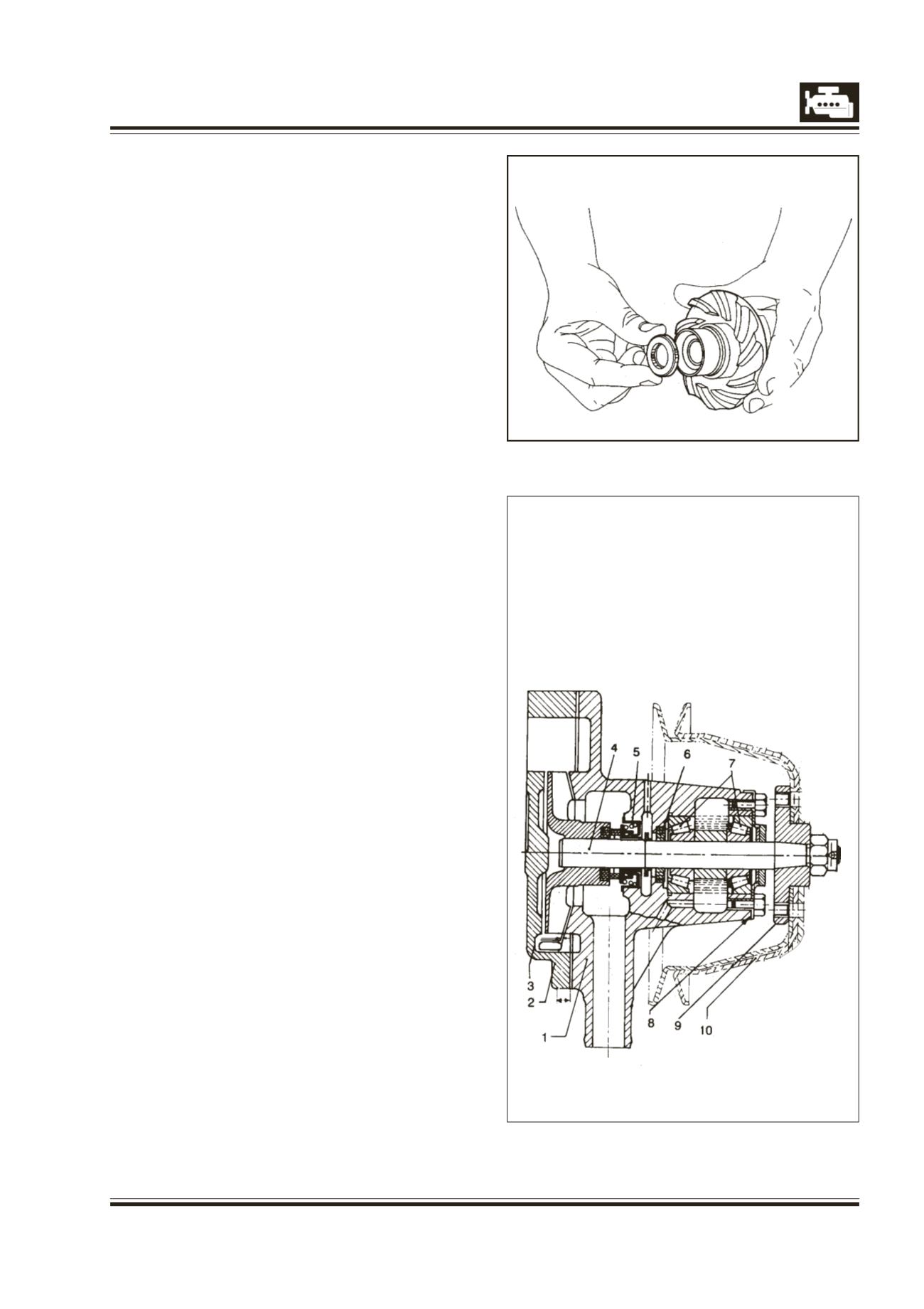
Fig. 5
Fig. 6
1. HOUSING
2. BACK COVER
3. IMPELLER
4. SHAFT
5. WATERSEAL
6. GREASESEAL
7. TAPE ROLLERBEARING
8. COVER PLATEWITHGREASE SEAL
9. HUB
10. PULLEY
8 Remove insert with its rubber sleeve from
impeller. Fig. 5.
9 Remove water seal from water pump housing.
10 Clean thoroughly and inspect all parts.
ASSEMBLY OF WATER PUMP
Fig. 6
Check condition of insert, rubber sleeve for insert etc.
If necessary, replace.
Inspect water pump housing, shaft, bearings and
impeller for damage and wear. Replace parts, if
necessary.
1 Fit new grease seal (with felt) in water pump
housing.
2 Fit new water seal into housing using drift, 2506
5890 99 02.
3 Fit outer race of inner bearing in water pump
housing using special tool, Part No 312 589 03 39
or 3574 5890 99 04.
4 Apply graphite oil on shaft, slip on slinger on the
shaft and slide it down till it stops on the step of
the shaft.
It is desirable to have a fixture for water pump
assembly. The hole for water pump shaft in the
fixture should be 7.5 mm deep and have 17 mm
dia. The 7.5 mm dim. is extremely important since
it determines the position of the fan hub in relation
to the housing.