


 1299 / 1526

ENGINE
131
Fig. 1
Fig. 3
1 2
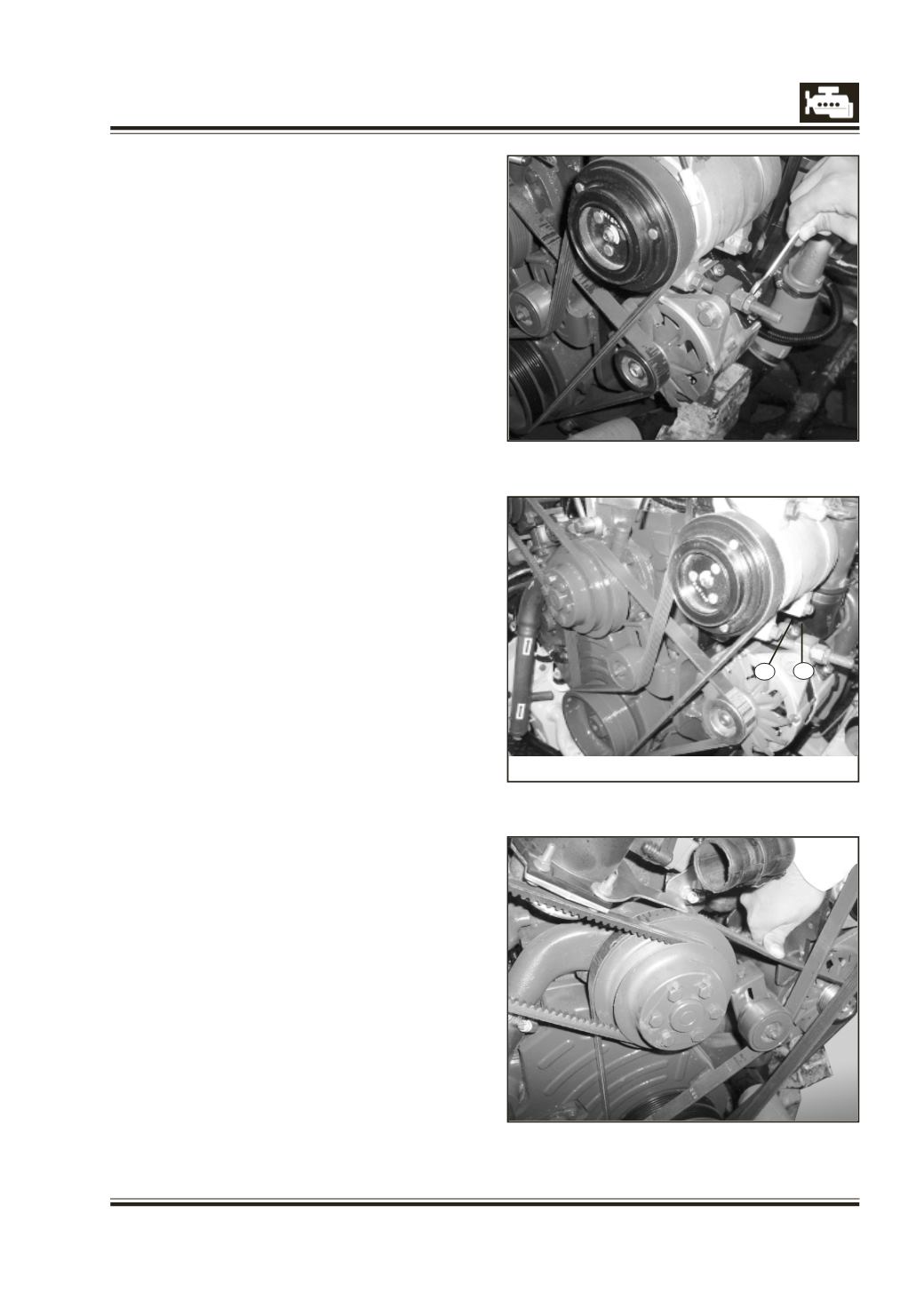
B) ALTERNATOR
REMOVAL
1 Disconnect cable from terminals on the alternator
making note of the terminal designations and
colour of the connecting cable so that they can
be reconnected in the same position.
2 Loosen alternator mounting screws and adjusting
lever. Swivel the alternator towards engine and
remove poly ‘V’ belt from the alternator pulley. Fig. 1.
3 Unscrew mounting bolts of alternator and remove
it.
INSTALLATION
1 Install alternator in the reverse order of removal.
2 Adjust belt tension such that centre of the vertical
portion of the belt should yield by about
9 to10 mm under thumb pressure. Fig. 2 & 3.
3 Tighten mounting bolts firmly over spring
washers.
NOTE
Testing and major overhaul of alternator is
detailed in Electrical Group.
Fig. 2
1. LOCK NUT
2. ADJUSTING NUT