


 1240 / 1526

ENGINE
72
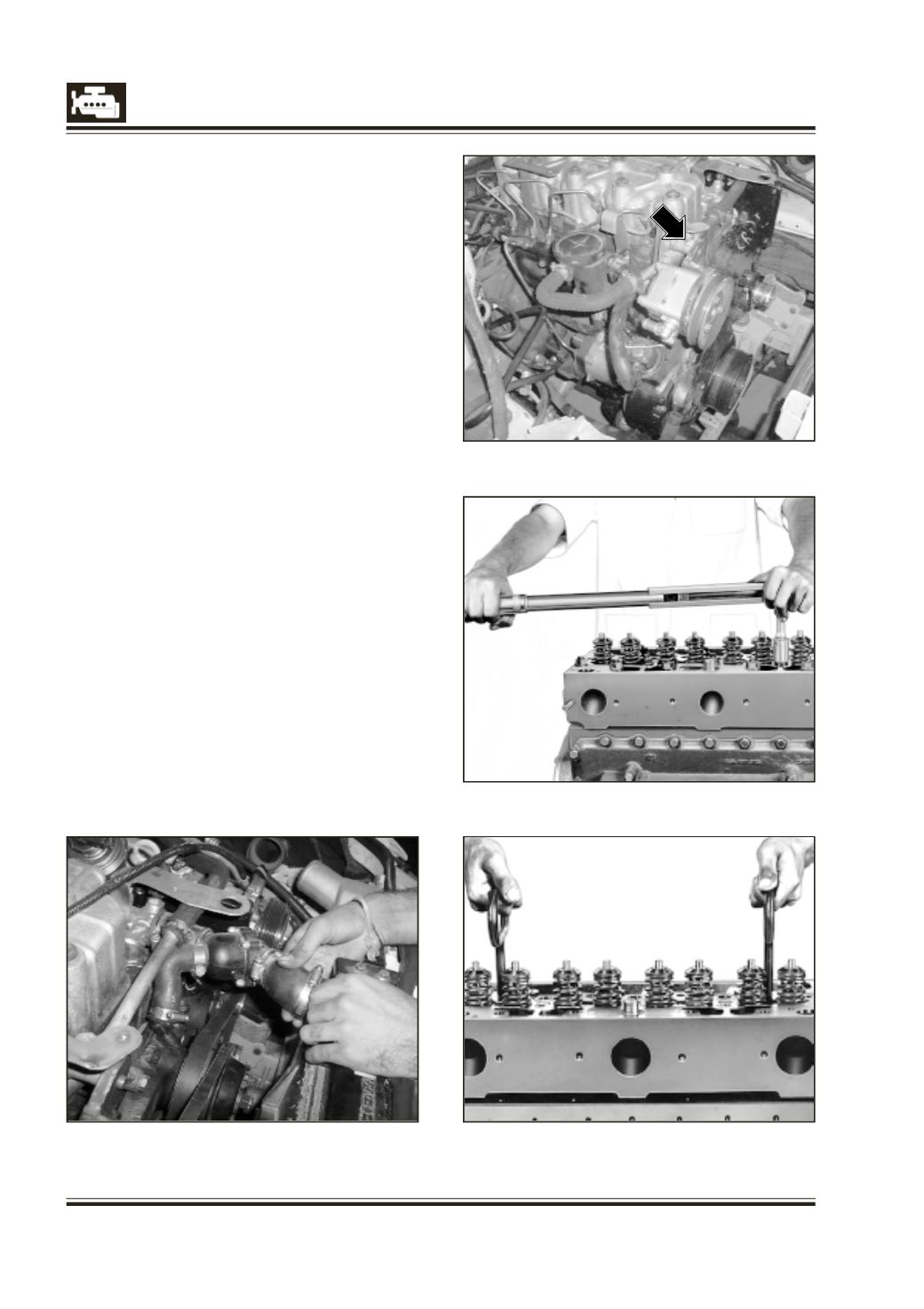
Fig. 2
Fig. 3
Fig. 4
Fig. 1
CYLINDER HEAD, COVER, ADJUSTMENT OF
VALVE CLEARENCE
CYLINDER HEAD REMOVAL
Ensure following components are removed before
removal of cylinder head: -
Cylinder head cover, Air intake elbow, HP pipes, (pump
to rail and Rail to Injectors), leak-off lines from injectors,
rail and plug the ports on the rail, injectors and keep
the parts in a clean place to avoid dust entry.
The air intake system pipes and hoses from
intercooler to air intake elbow should be removed
for accessibility to exhaust manifold and
turbocharger.
1.
Remove upper water cooling line and
thermostat hoses. (fig. 1).
2.
Slacken the belt tension on the power steering
pulley and remove the belts.
3.
Remove the power steering subassembly with
the bracket. (fig. 2).
4.
Remove EGR connections and EGR valve as per
procedure.
5.
Do not remove Injectors and claw of the
injectors if Nozzle Tip Protrusion (NTP) is to be
measured. ELSE Claws and Injectors to be
removed from cylinder head to avoid any
damage to Injectors after cylinder head
removal. Nominal value of NTP= 1+/- 0.25 mm.
6.
Disconnect the Exhaust System from the
exhaust down pipe.