
ELECTRICAL
215
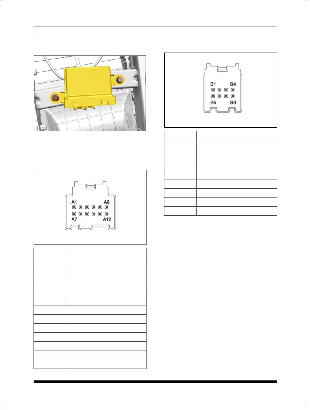
3. Remove the mounting bolts and take out the
controller unit.
REFITMENT
Follow the removal process in reverse.
PINOUT DETAILS
1.
Position A connector
PIN
DESCRIPTION
A1
FRONT PP ENABLE
A2
NC
A3
NC
A4
PP ENABLE LED
A5
REV. GEAR
A6
NC
A7
KL15
A8
NC
A9
CAN_H
A10
CAN_L
A11
NC
A12
GND
2. Position A connector
PIN
DESCRIPTION
B1
SENSOR 8
B2
SENSOR 9
B3
NC
B4
NC
B5
USENS
B6
SENSOR 10
B7
SENSOR 11
B8
GND SENSOR


