
BRAKES
13
A. BRAKING WITHOUT ABS IN OPERATION:
In case of normal braking operation when no
wheel speed differences are detected and neither
ABS nor EBD are active, when the driver presses
the brake pedal, brake pressure developed in
tandem master cylinder (TMC) reaches to each
wheel through hydraulic control unit (HCU).
During this phase, both inlet & outlet solenoid
valves are switched OFF (or not excited) by the
ECU. Hence the inlet valve is open and outlet
valve remains closed allowing the brake fluid to
flow freely through the inlet valve and to the
relevant wheel.
When the driver releases brake pedal, the brake
fluid flows back from the wheel, through the
respective one way valve towards TMC.
Solenoid
valve
Electricity
status
Valve
open
Open- close
channel
close
INLET
OFF
OPE
N
Master
cylinder
Wheel
cylinder
OUTLET OFF
CLOS
E
Wheel
cylinder
Reservoir
B.
BRAKING
WITH
EBD
INTO
OPERATION:
In case of a braking where the ABS ECU detects
a slip difference between the front and rear
wheels, EBD comes into operation. If the
difference in wheel slip between the front and rear
wheels exceeds a predetermined threshold the
ABS activates the pressure inlet valves for the
rear wheels, closing the valves and preventing
further pressure build up at that rear axle.
If during the braking event, this slip ratio between
the front and rear axle reduces below the
threshold level the inlet valves will be de-activated
and switch back to their normally open state
allowing further pressure increase at the rear axle.
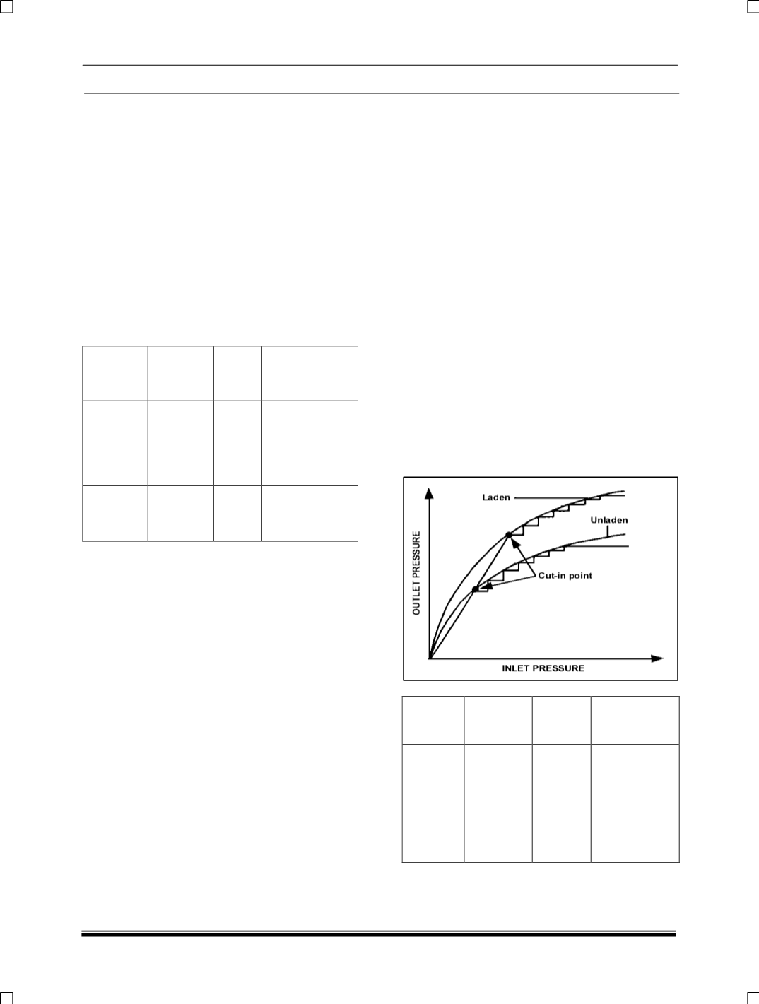
In this way the rear axle can follow more closely
to the Ideal braking force distribution curve for the
rear axle.
If the driver releases the brake, the inlet valves
will be deactivated and fluid can return to the TMC
via the inlet valve and the one way valve.
EBD control only acts upon the rear axle and can
only limit pressure being applied to a rear wheel, it
cannot perform pressure reductions.
Solenoid
valve
Electricity
status
Valve
open
Open- close
channel
close
INLET
ON
CLOSE
Master
cylinder
Wheel
cylinder
OUTLET
OFF
CLOSE
Wheel
cylinder
Reservoir
Fig: Pressure increase on rear axle following
ideal brake force distribution curve.


