


 138 / 310

ENGINE
92
2.1.3.5 ENGINE ASSEMBLY
1. Measure piston projection above crankcase with
the help of piston topping dial gauge.
2. Based on the piston projection / protrusion values
above crank case, select correct thickness of cyl-
inder head gasket. Refer the table.
Piston Projec-
tion (mm)
Gasket Thick-
ness (mm)
Identification
0.56 to 0.64
1.3
1 Notch
065 to 0.73
1.4
2 Notches
0.74 to 0.82
1.5
3 Notches
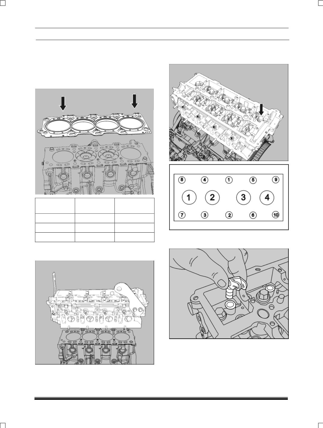
3. Install cylinder head on cylinder block by locating
the dowels properly.
4. Tighten the cylinder head mounting screws to
specified torque in the proper sequence as shown
below.
5. Install the roller finger follower and hydraulic lash
adjuster assemblies.
NOTE
•
Do not assemble spongy HLA’s.
•
Refer lubrication section for inspection details.