


 1260 / 1588

ENGINE
61
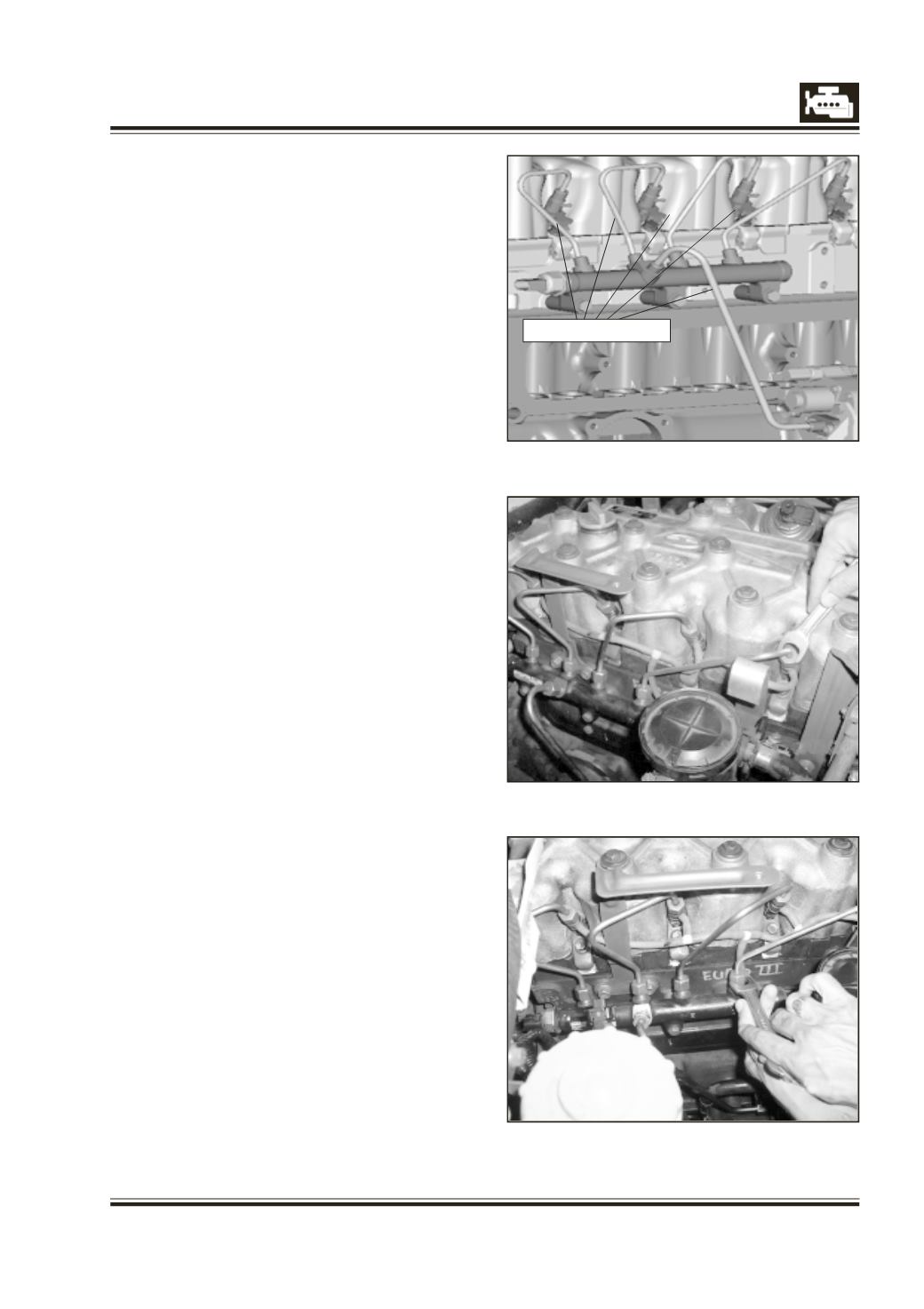
Fig 1
Fig 1A
HP PIPES
l
High Pressure Lines: -Pipe routing changed with
different material specification to suit new FIE
and to suit high pressure application.
l
4 Nos. (Rail to Injectors) and 1 (Pump to Rail).
l
Leak-off lines (Over flow lines): -Flexible Leak-off
lines on Injectors and HP pump.
Technical Description
l
Pump to rail: - length 364 mm
l
ID 3 mm, OD 8 mm
l
Rail to Injectors: - 4 Nos. Length 246mm each.
l
ID 2.4 mm, OD 6mm.
l
Material: - Steel with Zinc Plating, Pressure
range: - 0 to 1600 bar.
l
Cleanliness: - class1
l
Clean the HP connector nuts with solvent
applied using a clean brush.
l
Remove particles with a vacuum cleaner.
HP pipes removal procedure (Rail to Injectors)
1. Unscrew the cap nuts with a suitable 17 mm
spanner of the HP pipes first from the rail and
then from the Injectors.
NOTE
: Apply the torque to the upper half of the
nut in order to avoid damaging it.
(Fig: - 1 and Fig: - 1A)
2. Plug the respective ports on the rail and
injectors depending on which HP pipes are
removed. This is to avoid dust entry.
(Fig: 2)
3. DISCONNECTING THE PIPE FROM THE RAIL. Keep
the pipe nipple in contact with the rail cone
with one hand and completely unscrew the nut
with the other. While maintaining the pipe
nipple in contact with the rail cone, vacuum any
contaminants from between the pipe and the
rail cone.
4. DISCONNECTING THE PIPE FROM THE INJECTOR.
Keep the pipe nipple in contact with the
injector cone with one hand and completely
unscrew the nut with the other. While
maintaining the nipple in contact with the
injector cone, vacuum any contaminants from
between the pipe and the injector cone.
(Fig: - 3)
High pressure pipes