


 1255 / 1588

ENGINE
56
Fig 1
Fig 2
Fig 3
RAIL
Product Description:
l
Reservoir of fuel
l
Integrated pressure sensor
Technical Description
:
l
Maximal pressure in normal operating
conditions: 1600 bars
l
Up to 1800 bar operating pressure
l
Maximum pressure failure conditions: 2000 bars
(limit of the pressure sensor)
l
high
pressure
sensor
operating
from
0 to 2000 bars, located at the end of rail
l
High Pressure Volume of 19.5 cc to prevent
excessive changes in rail pressure during each
injection cycle.
l
high pressure sensor connector : FCI 3 way type
flying connector
l
Rail volume is also sized to ensure rapid build-
up during engine cranking
Removal of Rail
The rail has to be removed in case of the following
reasons
l
In case cylinder head has to be removed and
disassembled.
Precaution
The rail can perform 10 assembly / disassembly
cycles of pipes without any damage.
Removal
1. Remove if necessary with proper care other
components for accessibility to the common
rail.
2. Clean the surrounding area of the rail and HP
lines and the pump with pressurized water to
avoid dust and dirt entry in the rail after it is
removed.
3. Follow the HP pipes removal procedure.
4. Keep the rail in a clean place to avoid contact
with dust and dirt. Plug the inlet and outlet
ports immediately, where the coupling nuts of
HP pipes are mounted.
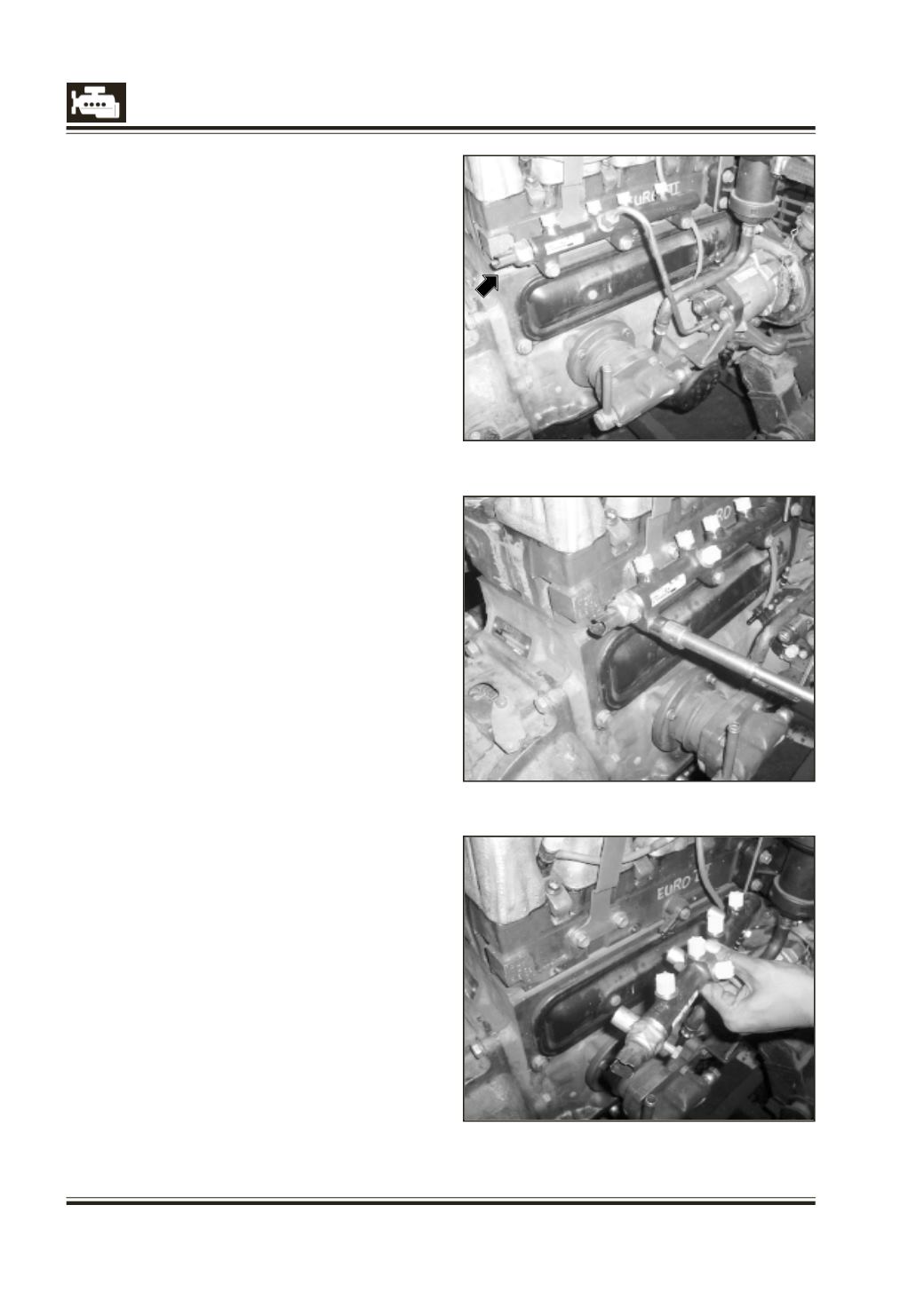
5. Disconnect the electrical connections on the rail
(fig. 1).
6. Unscrew the screws (3 Nos.) for mounting the
rail (fig. 2).
7. Remove the rail along with the spacers.
(3 Nos. fig. 3).