


 1327 / 1428

STEERING
21
Toe settings affect three major areas ofper-
formance:
(a) Tyre wears
(b) Straight-line stability and
(c) Vehicle handling characteristics
In case of TATA NANO, ONLY TOE IN adjustment is
required.
Following precautions are to be taken before com-
mencing wheel alignment:
1. Car should be unladen and parked on level sur-
face.
2. Front and rear tires should be inflated to correct
pressure (28 and 30 psi respectively)
3. Ensure that bushes in the front/rear suspension
are in satisfactory condition.
4. Ensure that front rear & suspension fasteners are
tightened to their specified torques.
5. Also ensure that there is no visible damage to any
of the suspension parts like lower link bushes and
struts.
6. Ensure that there is no play in steering linkages
and suspension ball joints.
7. Ensure no tyre wear on any wheels. If so replace
the respective tires.
Procedure for steering geometry adjustment
(wheel alignment) on vehicle:
Front wheel alignment data (Unladen condition
Camber angle
1.0° (+ve) (fixed)
Castor angle
7.4°(fixed)
Toe-in
15’ ± 5’
Wheel lock angle (Outer)
37°
LH/RH variation in castor
45'
Rear wheel alignment data (Unladen condition)
Camber angle
0.75° (+ve) (fixed)
Toe-Out
9’(fixed)
NOTE:
a) Please followmanufacturer’s (of tire replacement
machine)manual for wheel alignment instructions,
recommendations and any other additional
information.
b) All adjustments for wheel alignment are tobe done
inUNLADENCONDITIONONLY.
c) Only TOE INvalue atfronthas tobe adjustedwhile
doing wheel alignment. Restof thevaluesremains
fixed i.e. NOadjustmentsare required. Refer thegiv-
entable for standard values.
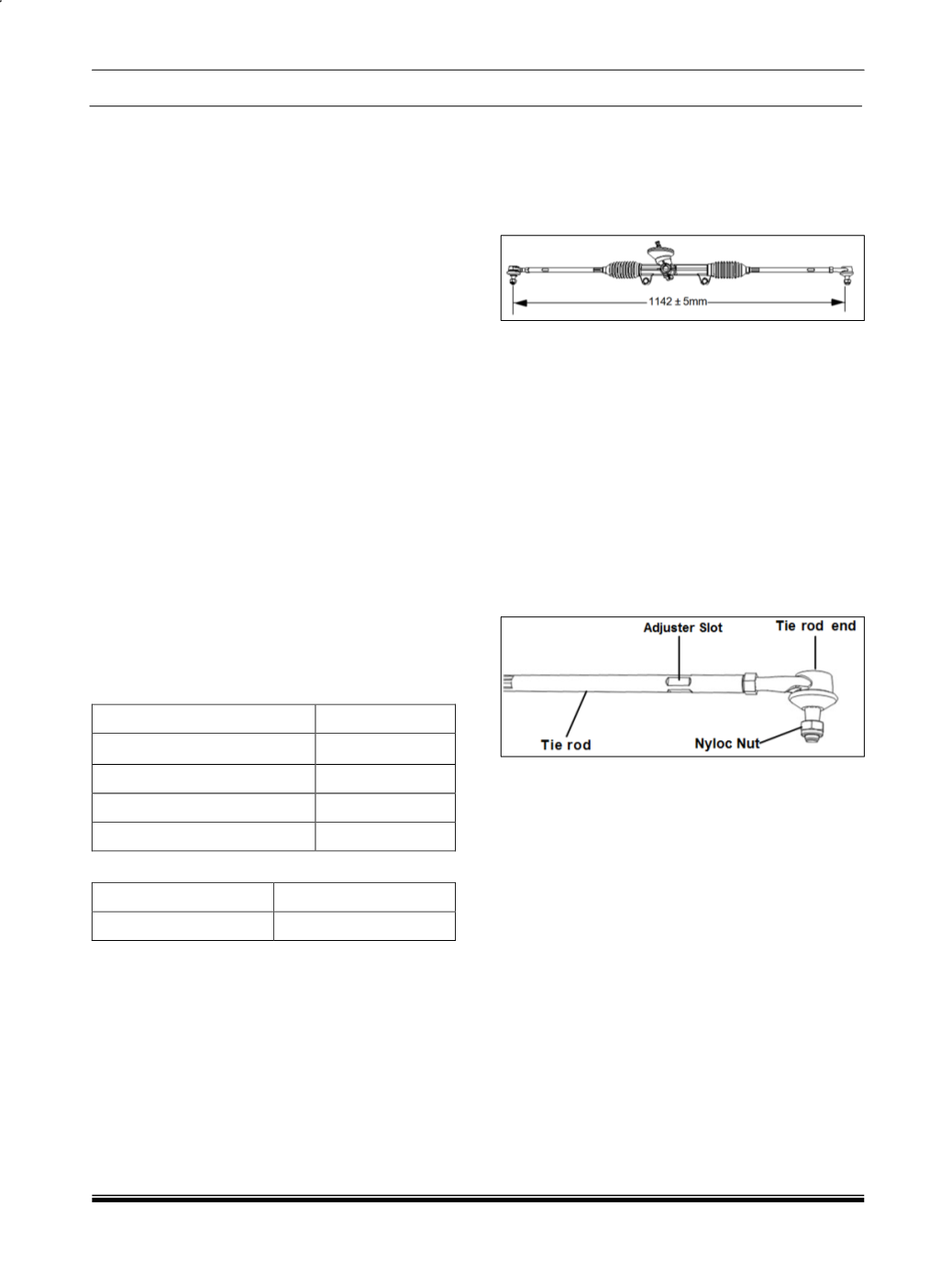
1. Steering rack & pinion gear comes with 1142
mm (nominal) length between centers of the ball
joints with tie rods parallel to the rack. (As shown
in following figure) Ensure that number of
threads of outer ball joints exposed out of the tie
rod tube is same on LH and RH side.
2. Rotate the steering wheel from lock to lock.
Measure the number of turns.
3. Bring the steering gear to centre by rotating
through half the number of measured turns.
4. Remove the steering wheel & refit it so that
spokes & mascot (T-emblem) are correctly posi-
tioned.
5. Ensure that both front tires are in straight ahead
position. Tighten the steering wheel nut to speci-
fied torque.
6. Fix the outer ball joints into the steering arm of
suspension and rotate the steering wheel to
bring the spokes to the correct position.
7. Adjust toe-in as given below.
a) Toe-in is adjusted by varying the length of tie
rods after loosening their lock nuts (as shown
in above figure). After adjusting the length of
tie rods recheck toe-in and tighten back the
lock nuts. Increasing length of tie rod will re-
duce the toe-in and vice-versa.
b) While adjusting toe-in, adjust the length of both
tie rods by rotating them in the same direction
such that their lengths remain equal at all
times.
8. Check thepositionof theT-emblemand the spokes
If the steering wheel is not centered, adjust the
tie rod lengthsby reducingoneand increasing the
other so that in the SAP (Straight Ahead Parked)
condition the toe is correct and yet steeringwheel
is centered.
NOTE:
After setting / adjusting steering geometry (i.e
Toe), connect the diagnostic tool and follow the
instruction for ECU learning. This is applicable
for all NANO variants fitted with EPAS.