


 1039 / 1428

ELECTRICALS
198
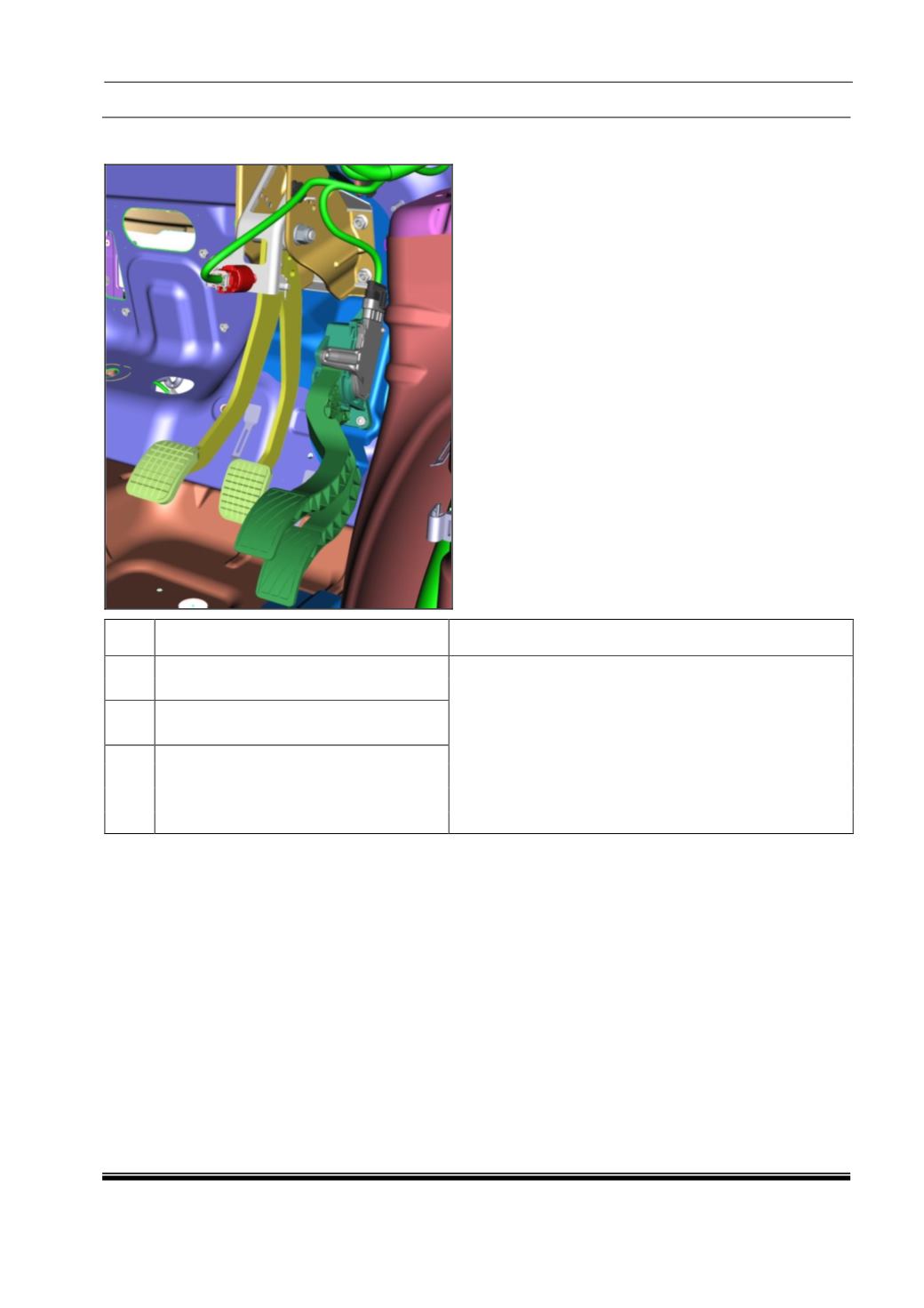
8.0 BRAKE SWITCH FAILURE CASES AND RECOVERY ON VEHICLE:
Sr.
No.
Failure Cases
Recovery on vehicle & TCU implementation
1
Brake switch connector Open / Brake
switch - Open pin 147 (NC contact)
1. After 5 ignition cycle (on/off: 1cycle = 30sec), EMS
send Brake switch signal is not correct on CAN, then:
a) TCU log DTC
b) Creeping disabled
c) Able to drive in all gears
2. Before five Ignition cycle, upshift will happened at
engine rpm @ 4500 in auto mode. Vehicle runs
normally in manual mode. (As TCU gets information
from EMS as brake pressed and signal correct).
2
Brake switch - Open pin 135 (NO
contact) and pressed brake
3
Brake switch open (both pin no 135 and
147)