


 387 / 1904

DRIVETRAIN
381
DRIVETRAIN
SHIFTER SHAFT AND SHIFTER FORK
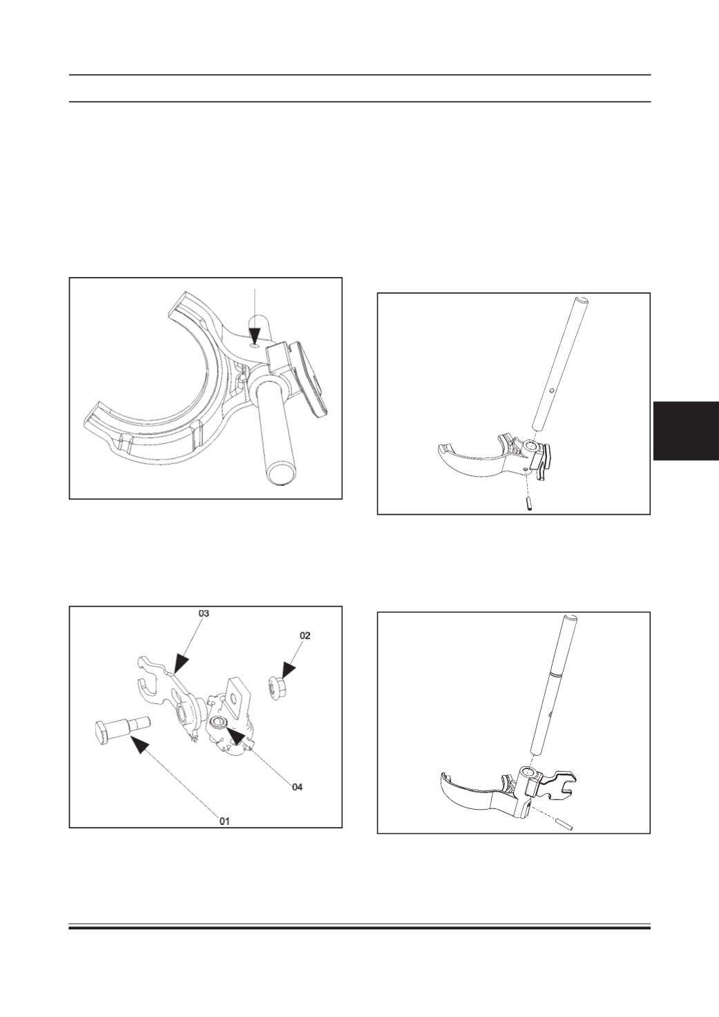
A. DISMANTLING
1 Position the first and second gear shifter shaft
assembly in a bench vice and remove the Dowel
pin and separate the shifter dog from the
assembly.
2 Similarly, dismantle the third and fourth gear shifter
shaft assembly and the reverse shifter shaft
assembly.
3 Dismantle the reverse gear shifter bracket by
unscrewing and removing thePivot (01), and flange
nut (02).
4 Remove the Reverse idler shifter finger (03) and
remove the detent assembly (04).
B. ASSEMBLY
1. Assemble the first and second gear shifter by
placing the shifter fork on its flat surface.
2. Insert the first and second gear shifter shaft such
that the shaft end closer to the slot goes into the
fork first as shown in the fig.
3. Then fit the dowel (spiral) pin such that it does
not protrude out from both ends by holding the
fork and shaft assembly in a vice and using a
suitable drift.
4. Assemble the third and fourth gear shifter by
placing the shifter fork in a flat surface.
5. Insert the shaft such that the slot goes into the
fork first followed by the groove.