


 263 / 1904

ENGINE 273 MPFI
257
ENGINE
Working Principle
The Piezo-resistive pressure sensor element and a
suitable circuitry for signal amplification and
temperature compensation are integrated on a silicon
chip. The measured pressure operates from above to
the active side of the silicon diaphragm. The
temperature sensor element is an NTC-resistor.
Installation Details
Following things must be kept in mind:
First cable mounting point must be located on the
sensor carrier, max. 150 mm (straight cable length)
after plug. Angle of bending the cable (deviation from
straight line) between cable and exit at sensor and
first mounting point: 20 - 90°. Admissible bending
radius of the cable up to the first cable mounting point:
R>50 mm.
Maximum diameter of the screw in the interior of the
mounting hole: 6 mm
Use washer dia. 10 mm or adequate screw head
diameter.
Use screw lock (e.g. Self locking screw).
Maximum permissible pressure at mounting flange is
20 N/mm
2
Storage Conditions
Storage Temp
-40°C to 130°C
Power rating at 25°C 100 mW
Max storage Time
3 Years.
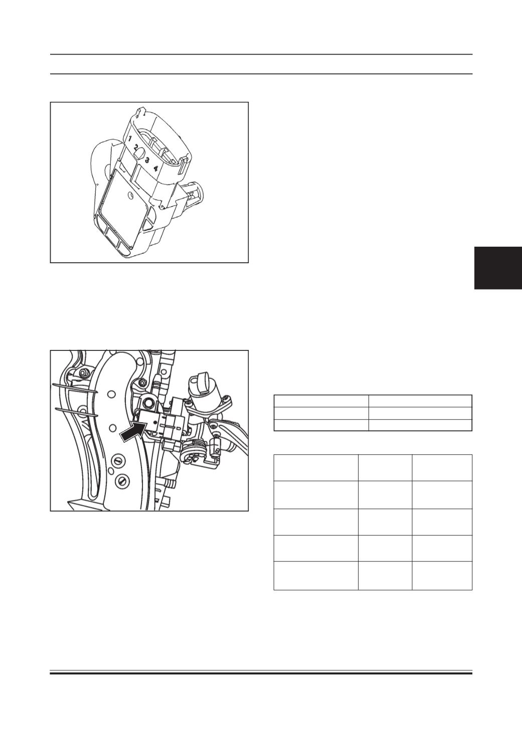
TMAP Sensor Pin Details
Signal
Connector ECU Pin No.
Pin No.
Manifold Pressure
Sensor Ground
1
42
ManifoldAir
Temperature Sensor
2
24
Manifold Pressure
Sensor Supply
3
7
Manifold Pressure
Sensor Signal
4
22
T-MAP SENSOR
Location
This sensor is fitted to the plane surface on Intake
Manifold.
Type
DSS3-TF