


 261 / 1904

ENGINE 273 MPFI
255
ENGINE
System Integration :
The sensor provides the crank shaft position input to
the ECU. The system uses a 36-2 = 34 tooth spaced
at 10 degree intervals. Target wheel has two tooth
missing (at 225 degree ATDC of cylinder 1) to allow
the engine position to be determined.
The sensor signal is used to calculate engine speed
& crank shaft position.
Stand Alone Diagnosis :
Refer 3.11.5 Trouble Shooting and Diagnosis.
SystemDiagnosis
•
Use TATADiagnostic Tool.
•
Check for engine RPM during cranking.
On vehicle Removal, Inspection & Refitment
Procedure :
Removal of Crank shaft position sensor
•
Remove the crank shaft position sensor.
Precaution :
Pull the connector after pressing the lock.
•
Remove the bolt of the crank shaft position sensor
with the help of ring spanner.
Refitment of Crank angle sensor :
•
Refit the bolt of the crank shaft position sensor.
•
Refit the crank shaft position sensor.
Inspection of crank angle sensor :
•
Check the resistance of crank shaft position
sensor. (Acceptable
value 890 +/- 89 Ohm)
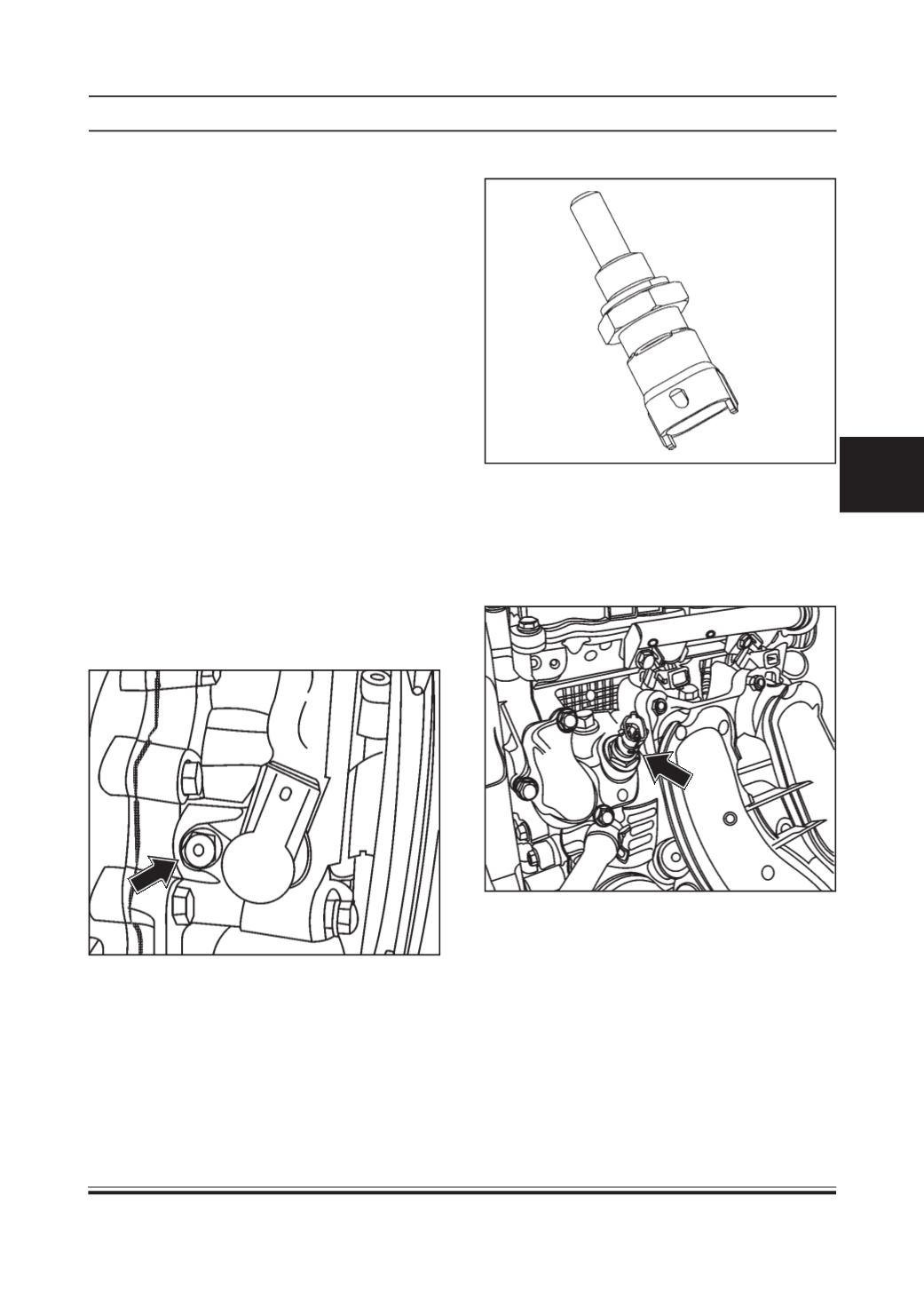
COOLANT TEMPERATURE SENSOR
Type
TF-W
Location
Coolant Temperature Sensor is fitted on cylinder head
near thermostat.
Working Principle:
The temperature sensing circuit uses Thermistor that
is sensitive to change in temperature. It has basically
the NTC (Negative Temperature Coefficient) means as
the temperature increases as the resistance
decreases.
Installation Details:
Installation Torque: - 18 to 25 Nm (Excessive torque
may lead to shear of sensor)