


 1238 / 1904

ENGINE
11
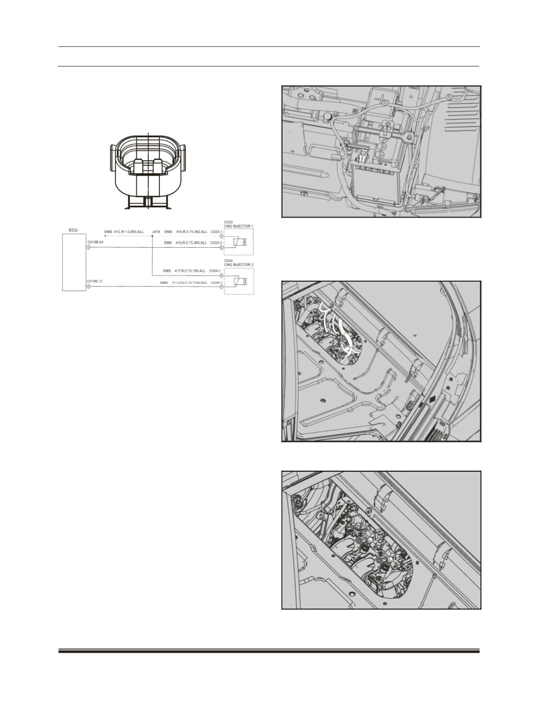
8. Pin detail / assignment:
ECU pin 224: Injector 1 – Pin 2
ECU pin 212: Injector 2 – Pin 2
Supply - Pin 1 of all injectors (power relay)
Circuit Diagram:
Removal & Refitment:
Removal:
NOTE:
Park the vehicle with brakes ON and duel
selector switch is kept in CNG mode.
Manually turn of the tank valve and connect
the TML tester tool and start the service
“Empty CNG lines”.
Crank the engine and run in idle condition
until engine stop at its own.
Re crank the engine it should not start (tank
pressure should be 0 bar)
WARNING:
Do not turn OFF Cylinder Valves, in vehicle
running in CNG mode. This may wrongly
detect the leakage error.
Disconnect the battery negative cable.
Remove the Engine access window( For that
refer the removal Refitment of Engine Access
window.
Disconnect all electrical connection of
injector’s.
Remove M6 screw used for mounting Gas rail
on intake manifold.