


 687 / 1575

BRAKES
33
BRAKES
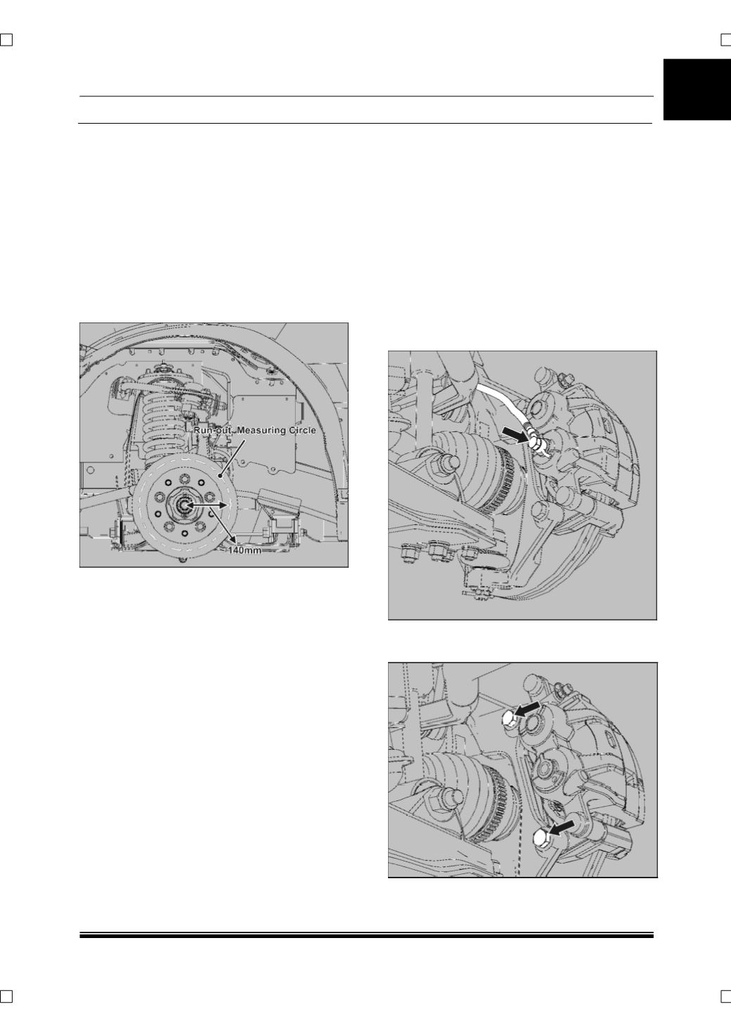
I. DISC RUN-OUT MEASUREMENT
PROCEDURE
1. With the gear in neutral position, hoist the
vehicle on two post lift and remove the front
wheel.
2. Mount the magnetic dial stand at an
appropriate position such that the needle can
be placed perpendicular to the disc face.
3. Ensure that brake disc surface is clean and
dial indicator tip touching the brake disc on
circle at a distance of
≈
140mm from wheel
centre.
4. Rotate the brake disc while watching the dial
indicator needle movement; record the
maximum value shown on the dial indicator.
The maximum value is the brake disc run out.
5. The brake disc runout should not be more than
0.130 mm (130 Microns).
NOTE
For 4x2 vehicle the front brake disc runout should
not be more than 0.08 mm.
6. Same procedure to be repeated for rear brake
disc.
(Ensure parking brakes are released.)
NOTE
For further inspection and repairs refer the
BRAKE DISC REMOVAL in the next section.
6.1.2.3 ON VEHICLE REPAIRS
A. CALIPER ASSEMBLY WITH CARRIER
REMOVAL
1. Apply parking brake & keep the gear shift lever
in neutral position.
2. Jack up the front of the vehicle and remove
wheels.
3. Remove hose from caliper body by taking out
the banjo bolt and collect the brake fluid from
caliper in a clean container. Block the brake
hose using a dust cap to prevent loss of brake
fluid and prevent contamination and keep the
pipe in the vertically up-straight position.
4. Loosen and remove the mounting bolts of
caliper assembly.