


 545 / 1575

FRONT AXLE (4X4)
31
FRONT AXLE
(4X4)
PINION POSITION SHIM SELECTION
1. Pinion position shim selection can also be done
using a special tool, in the absence of removed
ring/pinion gear.
2. Install pinion height set master block which is part
of tool
(Part No. 287058903310)
over pinion inner
bearing cup seat.
3.
Set the dial gauge to 0
(zero)
, on surface plate.
Install dial gauge on pinion height gauge which is
again a part of tool
(Part No. 287058903309)
4. Install pinion height set gauge with dial gauge on
side bearing seats. Ensure that plunger of dial
gauge touches top face of pinion height set mas-
ter.
5. Rock the depth gauge. Record the maximum
reading on gauge needle. Let it be X'
6. To calculate shim thickness procedure as follows:
Shim thickness required = X– etched value on
pinion
(when etched POSITIVE)
Shim thickness required = X + etched value on
pinion
(when etched NEGATIVE)
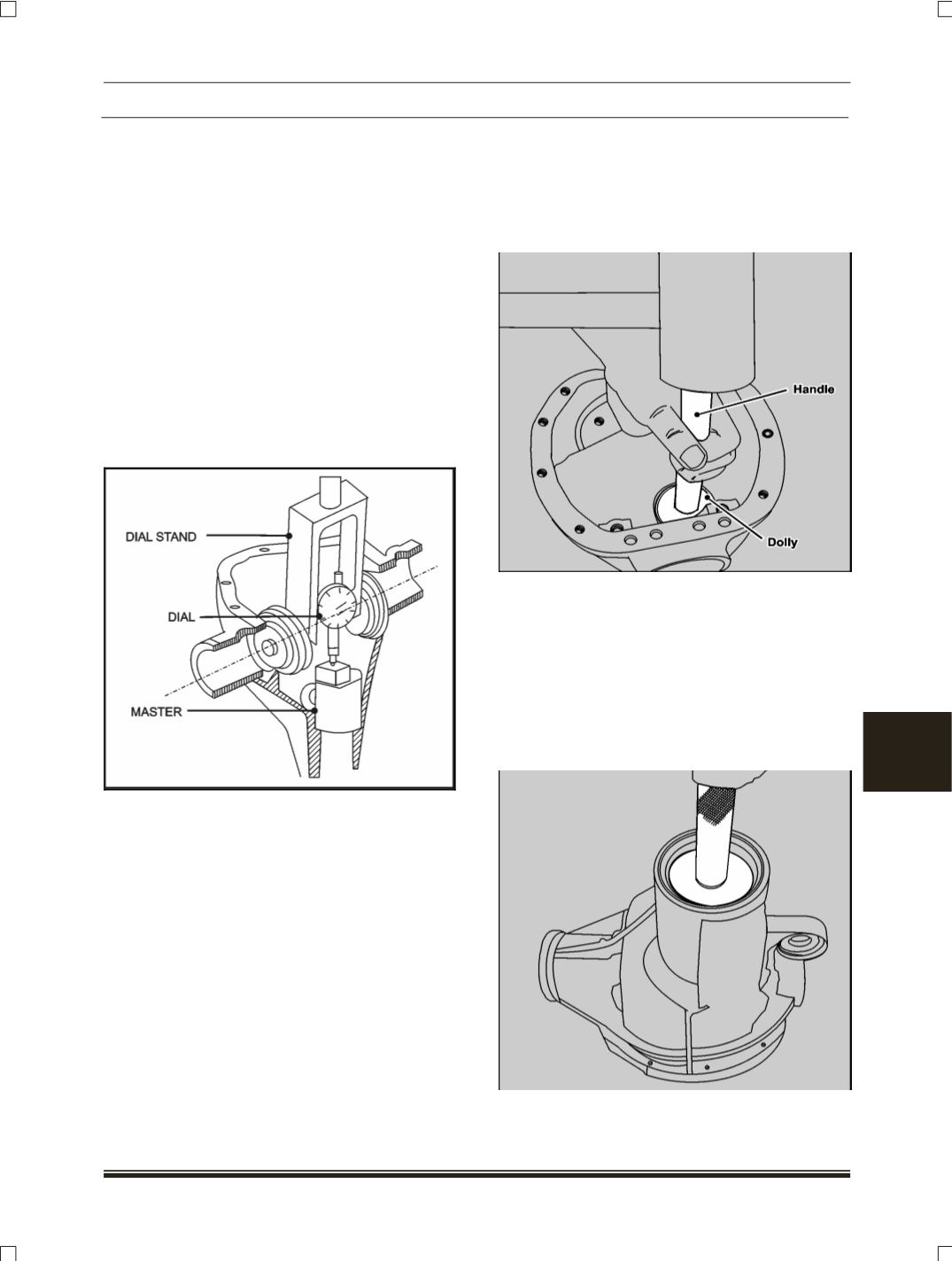
ASSEMBLY
1. Press the bearing in carrier using a dolly.
(Part
No. 287058903304)
2. Drive inner bearing cup into carrier using tools
given below:
Installer dolly inner pinion bearing cup.
(Part No.
270458903321)
Handle
( Part No. 289458903501)
NOTE
In such a way that orientation of the baffle towards
the pinion oil gallery
.
3. Assemble outer pinion bearing cup and baffle into
carrier using tools given below:
Installer outer pinion bearing cup
(Part No.
270458903314)
Handle
(Part No. 289458903501)