


 396 / 801

FATC
9
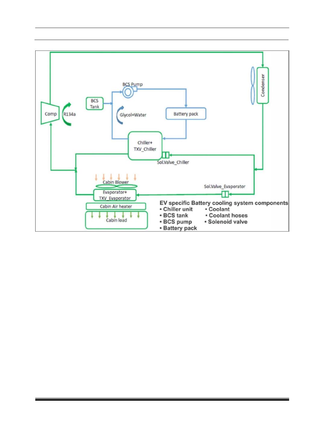
SCHEMATIC OF HVAC AND BCS
WORKING
The HVAC system is similar to a conventional auto-
motive HVAC system. It consists of a Compressor, a
Condenser, and an evaporator. System wise it can
be divided as low-pressure side and the high-
pressure side, which is divided at the evaporator,
more precisely at the expansion valve housed in it.
REFRIGERANT CYCLE
The compressor compresses the refrigerant R134a,
increasing its pressure and temperature. This high
pressure hot vapour is then made to pass through
the condenser
(condenser is cooled by the passing
ambient air)
, where it gives its latent heat to turn to
liquid, the drop in temperature is small, as most of
the heat lost will be latent heat resulting in change of
state to liquid.
A receiver drier which is integrated in the condenser
is used to filter out the moisture and also allows only
liquid to flow further to the Thermal Expansion Valve
(TXV). The high-pressure low temperature liquid
then expands in the TXV Valve where the refrigerant
pressure drops considerably, which also results in a
drop of temperature.
This cold low pressure liquid is circulated through the
evaporator coil, where it absorbs the heat of the am-
bient air made to pass through it by forced circulation
of the blower. The liquid refrigerant absorbs the la-
tent heat required to change to vapour state and
turns to vapour. There is no considerable change in
temperature as the heat absorbed by the refrigerant
is only latent heat. This vapour then flows to the
compressor and the cycle continues.
BATTERY COOLING SYSTEM (BCS)
After condenser ‘T’ joint is provided in the refrigerant
line and refrigerant flows towards Chillier unit which
is used for battery cooling system.
The high-pressure low temperature liquid then ex-
pands in the TXV Valve where the refrigerant
pressure drops considerably, which also results in a
drop of temperature. This cold low-pressure liquid is
circulated through the chillier unit, where it absorbs
the heat of the coolant made to pass through it by
forced circulation of coolant pump. The liquid refrig-
erant absorbs the latent heat required to change to
vapour state and turns to vapour. Low pressure, su-
per-heated refrigerant flows towards compressor
suction.
Before compressor suction, one ‘T’ joint is provided
where superheated vapour refrigerant from cabin
HVAC and BCS chillier comes together and flows
towards compressor suction.