


 227 / 745

C635 TRANSAXLE
40
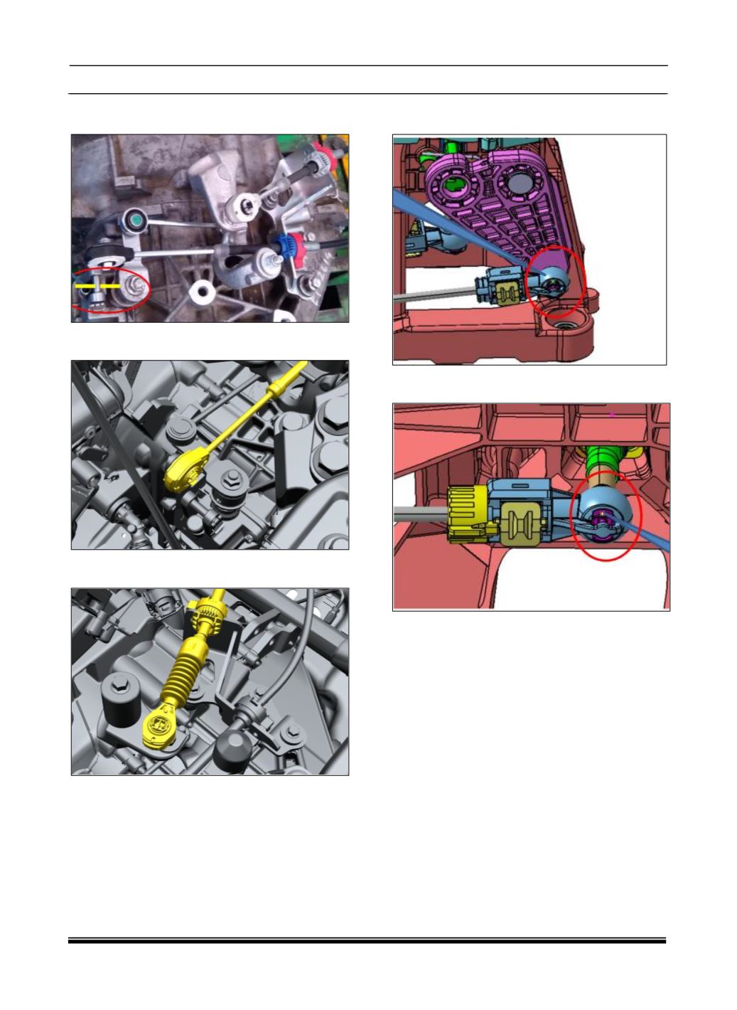
4. Ensure Transaxle is also locked in 1
st
-2
nd
plane
by locking pin on Top cover assy.
5. Fit Transaxle side select cable end on ball joint
of top cover select lever.
6. Fit Transaxle side shift cable end on ball joint of
counter weight assembly.
7. Fit shifter side select cable end on spherical ball
joint of select lever.
8. Fit shifter side shift cable end on spherical ball
joint of shift lever.