


 4897 / 4910

Immobilizer –DTC Troubleshooting Data
Version: 1.
2
Date:
03-June-2014
Prepared Author
:
Sarang K/Mithipati P
Review & approved by
: R A Rode (ERC-E&E)
Page: 54 of 67
Copyright ©
TATA MOTORS Ltd.
This document must not be used in any way, such as copying and redistributing to third parties, without the consent of author.
DTC’s confirmation:-
After rectification, ensure the following points using TML diagnostic tool before handing over to customer.
a) DTC should not be present in ECU memory.
Circuit Schematic Diagram: N.A
Component Location & Image:- N.A
Connector Location: N.A
DTC’s confirmation:-
After rectification, ensure the following points using TML diagnostic tool before handing over to customer.
a) DTC should not be present in ECU memory.
Circuit Schematic
Diagram:-N.AComponent Location & Image: - N.A
Connector Location: N.
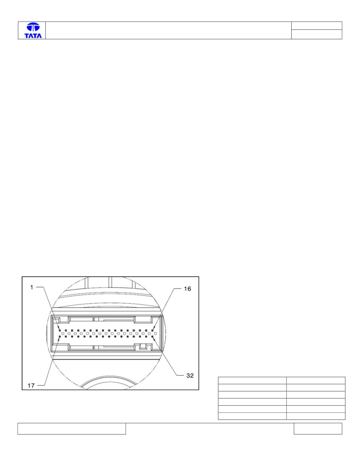
Connector View & Information: -
IPC ECU side connector diagram
IPC ECU Pin assignment:-
Description
ECU pin
CAN_H chasis
6
CAN_L chasis
5
Battery
1
Ignition input
22
Battery ground
24