


 4850 / 4910

Immobilizer –DTC Troubleshooting Data
Version: 1.
2
Date:
03-June-2014
Prepared Author
:
Sarang K/Mithipati P
Review & approved by
: R A Rode (ERC-E&E)
Page: 7 of 67
Copyright ©
TATA MOTORS Ltd.
This document must not be used in any way, such as copying and redistributing to third parties, without the consent of author.
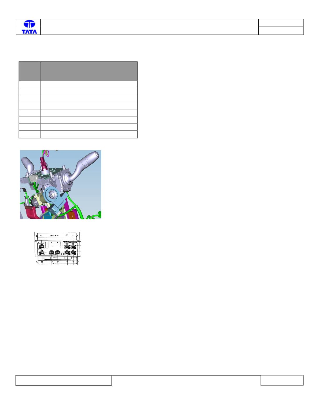
Circuit Schematic Diagram:
Refer the immobilizer schematic
VICM
pin
no
Pin description
1
Vbatt (KL30)
2
GND
3
CAN_H(High-speed)
4
Ignition (KL15)
5
Status LED
6
Trasport Mode Fuse (10A)
7
Battery Supply (+Vbatt)
8
CAN_L(High-speed)
Component Location & Image:-
Connector View & Information: -