


 4478 / 4910

Copyright ©
TATA MOTORS Ltd.
This document must not be used in any w ay, such as copying and redistributing to third parties, w ithout the consent of author .
SRS / Airbag
ECU – DTC Troubleshooting Guide
Version: 14.0
Date: 14-February-2017
Prepared by:Airbag COC Review &
Approved by:Sanjeev VM
Page: 209 of 549
IPC ECU Pin assignment:-
Description
IPC ECU Pin No.
CAN_H chassis
6
CAN_L chassis
5
Battery
1
Ignition input
22
Battery ground
24
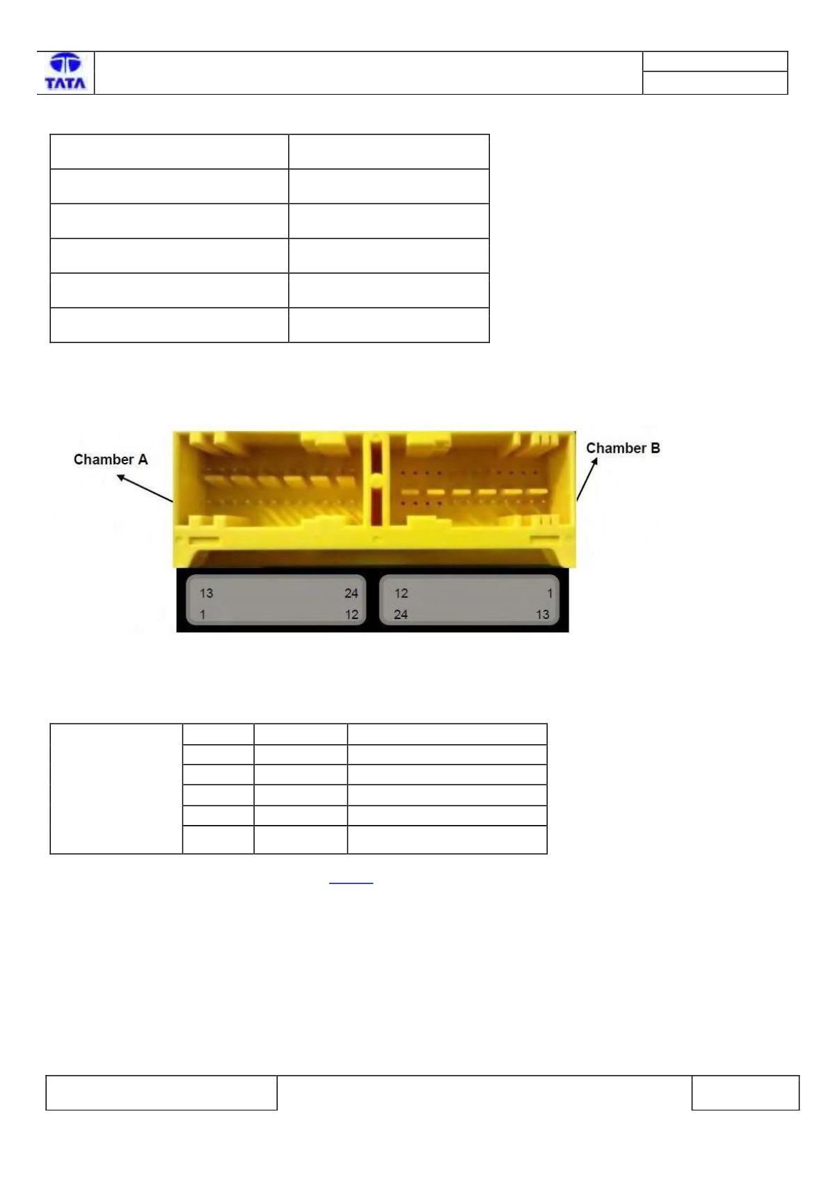
Airbag ECU side connector diagram:-
Fig195:- Airbag ECU connector interface.
Airbag ECU pin assignment:-
Pin No.
Pin Name
Description
1
CAN_H
CAN High
2
CAN_L
CAN Low
7
A_GND
Common Switch GND
12
Vbat
Supply Voltage Battery
23
GND
Power GND
Please refer Airbag ECU Pin Assignment on
Page 6 for more details.
.
Inspection Method:-
N.A.
CHAMBER A