


 4275 / 4910

Copyright ©
TATA MOTORS Ltd.
This document must not be used in any w ay, such as copying and redistributing to third parties, w ithout the consent of author.
SRS / Airbag
ECU – DTC Troubleshooting Guide
Version: 14.0
Date: 14-February-2017
Prepared by:Airbag CoC Review &Approved
by:Sanjeev VM
Page: 6 of 549
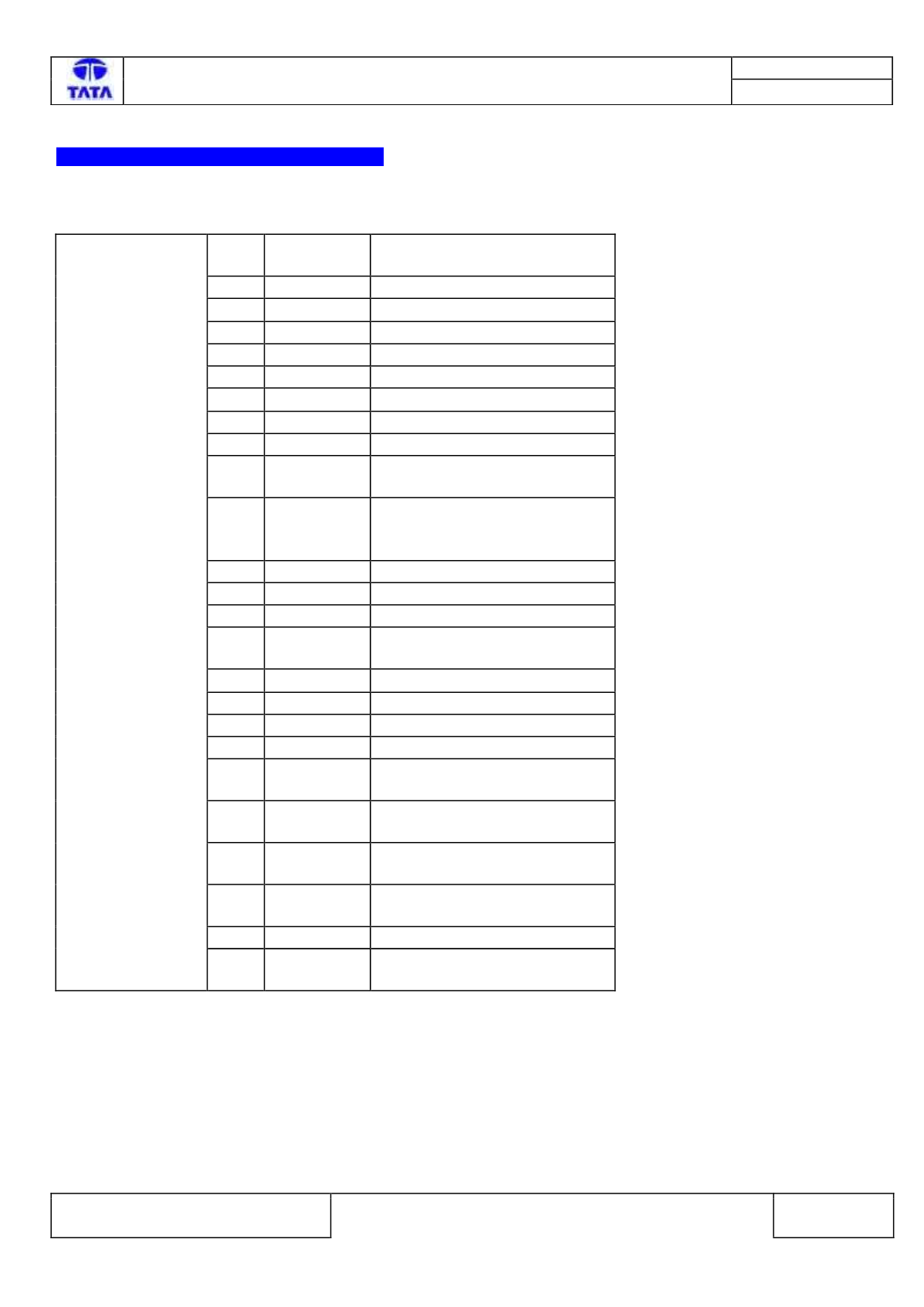
RCM (Airbag/ SRS) ECU Pin assignment
CHAMBER A :
Pin
No.
Pin Name
Description
1
CAN_H
CAN High
2
CAN_L
CAN Low
3
LSD
Low side driver
4
NA
Not Applicable
5
CRO
Crash Output
6
NA
Not Applicable
7
A_GND
Common Switch GND
8
BLRM
Rear Middle Buckle Switch
9
PADS
Passenger Airbag Deactivation
Switch
10
BLFP+PPD In
Series
Connection
of
Passenger Buckle Switch and
passenger detection mat.
11
NA
Not Applicable
12
V bat
Supply Voltage Battery
13
BLRD
Rear Buckle Switch Driver Side
14
BLRP
Rear Buckle Switch Passenger
Side
15
ABFD-
Front Airbag Driver, Minus
16
ABFD+
Front Airbag Driver, Plus
17
ABFP+
Front Airbag Passenger, Plus
18
ABFP-
Front Airbag Passenger, Minus
19
BTFD-
Belt Tensioner Front Driver,
Minus
20
BTFD+
Belt Tensioner Front Driver,
Plus
21
BTFP+
Belt Tensioner Front Passenger,
Plus
22
BTFP-
Belt Tensioner Front Passenger,
Minus
23
GND
Power GND
24
PADI
Passenger Airbag Deactivation
Indicator
CHAMBER A