


 4445 / 4910

Copyright ©
TATA MOTORS Ltd.
This document must not be used in any w ay, such as copying and redistributing to third parties, w ithout the consent of author.
SRS / Airbag
ECU – DTC Troubleshooting Guide
Version: 14.0
Date: 14-February-2017
Prepared by:Airbag COC Review &
Approved by:Sanjeev VM
Page: 176 of 549
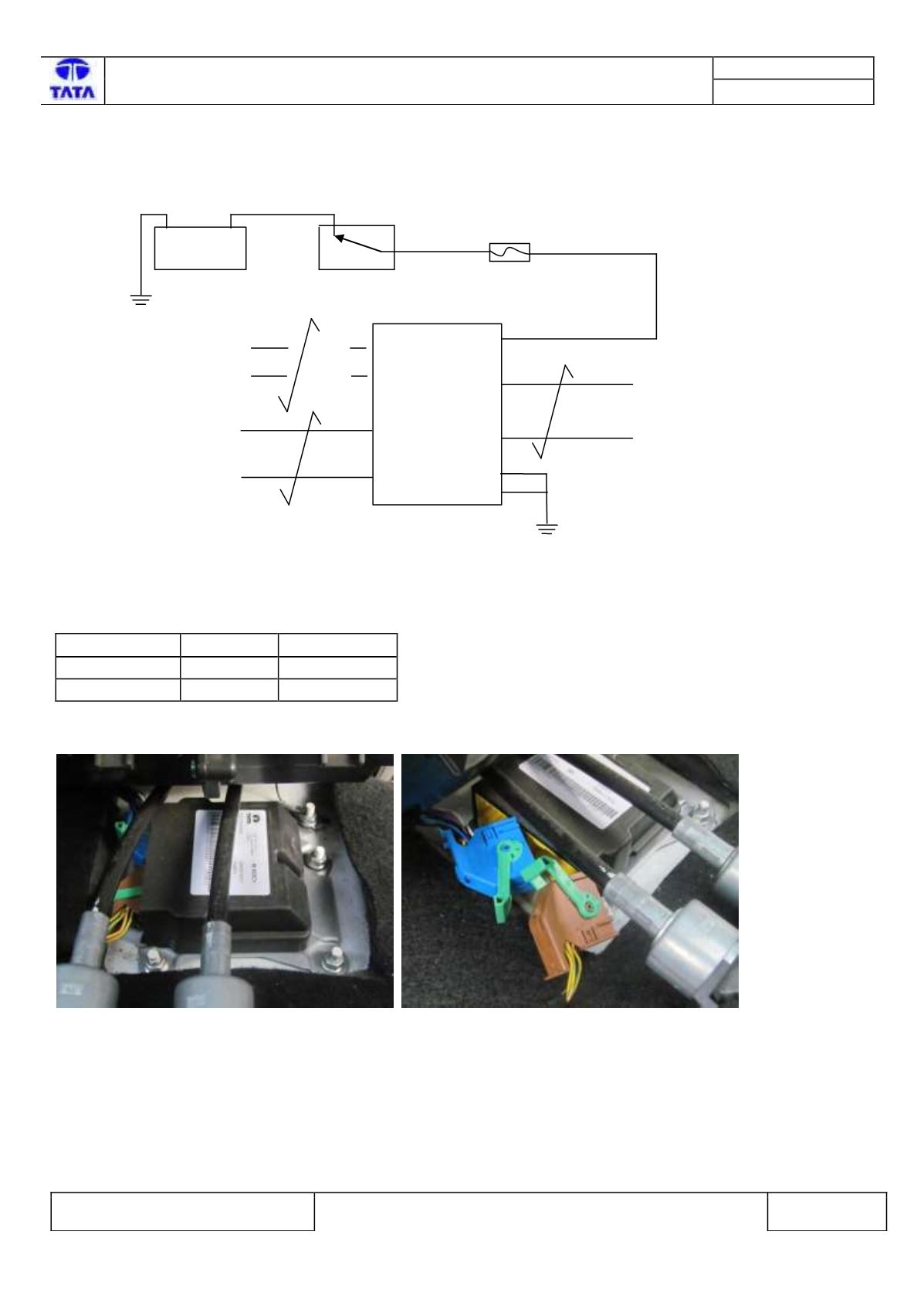
Circuit Schematic Diagram:-
Schematic shown below for illustration
Battery>>>>>Fuse>>>>Relay>>>>>>>Sensor/Actuator>>>>>ECU
Component Location & Image:-
The Chamber Coding & color are:
Chamber
Coding
Color
Chamber A
D
Blue
Chamber B
C
Brown
Airbag ECU is fitted in the floor of central console in the car.
.
+
V
12
Battery
A23
CAN H
Ignition Sw itch
CAN L
A12
A7
-
RESTRAINTS
CONTROL
MODULE
A1
A2
Fuse 10A
Vbat
Fig:169 Airbag ECU location Fig:170 Airbag Wiring Harness connector