


 4282 / 4910

Copyright ©
TATA MOTORS Ltd.
This document must not be used in any w ay, such as copying and redistributing to third parties, w ithout the consent of author.
SRS / Airbag
ECU – DTC Troubleshooting Guide
Version: 14.0
Date: 14-February-2017
Prepared by:Airbag CoC Review &Approved
by:Sanjeev VM
Page: 13 of 549
DTC’s confirmation:-
After rectification, ensure the following points using TML diagnostic tool before handing over to customer.
a) Clear the DTC’s & make sure no DTC’s are present for Airbag system
b) Check whether any new DTC’s are getting qualified for repeated cranking.
c) Ensure the Airbag Warning Lamp Indication is continuously ON in Instrument Cluster for
4 seconds
after
Ignition ON
d) Ensure the Airbag Warning Lamp Indication goes OFF after
4 seconds
from Ignition ON.
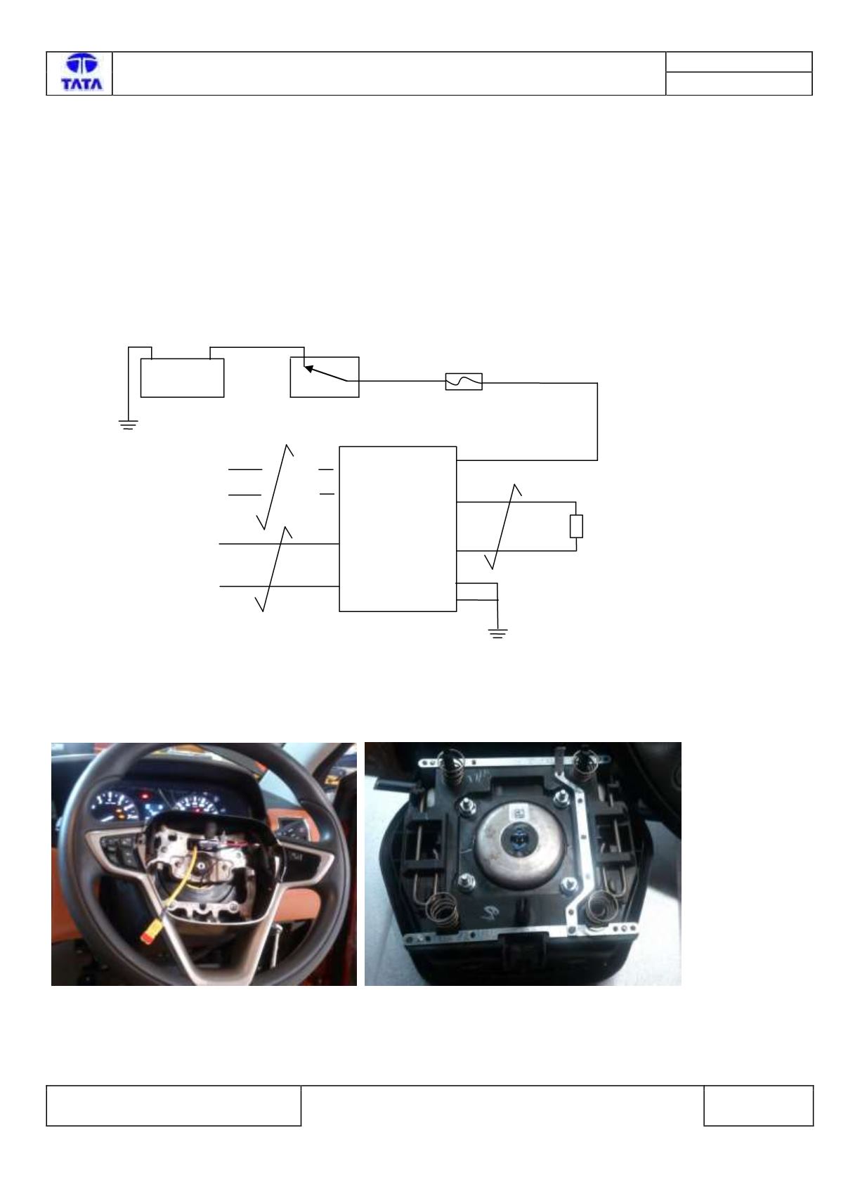
Circuit Schematic Diagram:-
Schematic shown below for illustration
Battery>>>>>Fuse>>>>Relay>>>>>>>Sensor/Actuator>>>>>ECU
Component Location & Image:-
+
V
12
Battery
A23
CAN H
Ignition Sw itch
CAN L
A12
A7
-
RESTRAINTS
CONTROL
MODULE
Driver
Airbag
A1
A2
Fuse 10A
A15
A16
ABFD-
ABFD+
Vbat
Driver Frontal Airbag connector is present inside the steering wheel.
Fig1:Driver Frontal Airbag connector location. Fig2: - Driver Airbag module