


 3932 / 4910

{Osprey CCM}
DTC Troubleshooting Data
Version: 2.0
Date: 28-Jul-17
Author: ERC
Page: 116 of 244
Copyright ©
TATA MOTORS Ltd.
This document must not be used in any way, such as copying and redistributing to third parties, without the consent of author.
DTC’s confirmation:-
After rectification, Fresh/Recirc button from control panel and ensure the following points by parameters using TML
diagnostic tool before handing over to customer.
a) Physical check of Fresh/recirc change when requested.
b) Read ECU parameter
Fresh Air/RECIRC Drive Motor A Output
Circuit Schematic Diagram:-
“Refer the circuit schematics from the tool”
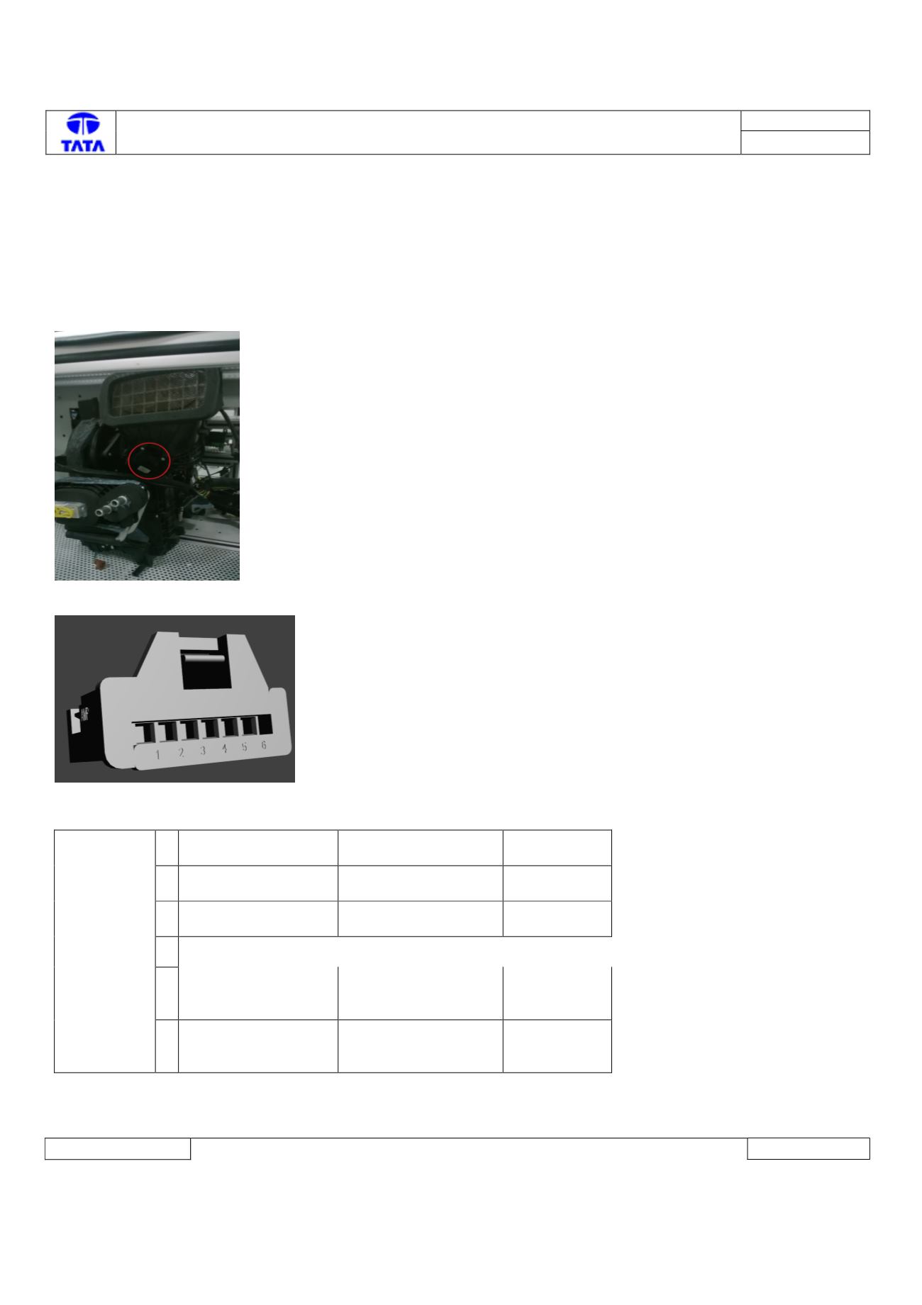
Component Location & Image:-
HVAC kit
Connector View & Information: -
Pin Details:-
C1
ACTUATOR
Amp no 0-
1355082-1
1
PotentiometerGnd
Potentiometer
Ground with FB-
Gnd
2
PotentiometerFbSig
Potentiometer
feedback signal
Analog
3
PotentiometerSpply
Potentiometer
Supply with FB-
Power
4
5
Mot +
Motor signal is + in
CW and Motor
signal is - in CCW
Digital
6
Mot -
Motor signal is - in
CW and Motor
signal is + in CCW
Digital
Inspection Method: -
NA