


 1336 / 4910

TML HARRIER Infotainment DTC Troubleshooting guide
Version: 0.3 Draft
Date: 17-Aug-18
Author:
Vijaya Bhaskar
B/Pritam Bansod
Page: 102 of 109
Copyright ©
TATA MOTORS Ltd.
This document must not be used in any way, such as copying and redistributing to third parties, without the consent of author.
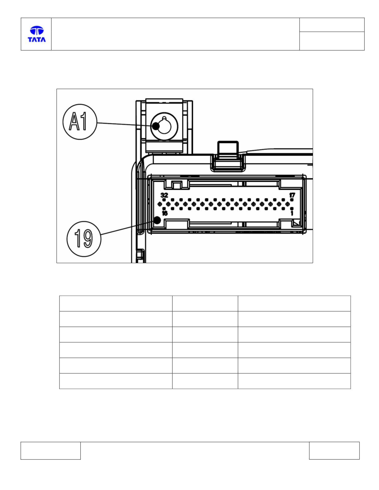
HVAC Control Module side connector diagram
HVAC Control Module Pin assignment:-
Description
Connector
ECU pin
CAN_H
C1
24
CAN_L
C1
22
Battery
C1
15,16
Ignition input
C1
31
Battery ground
C1
1,2