


 212 / 1906

ENGINE
176
TEST PROCEDURE
Use a d 3-½ digit Digital Multi meter (
DMM
) for
measuring the resistance.
Immerse the sensor in a water bath such that its
terminals are facing upwards and out side the
water level. (
See fig.)
Ensure that, around 50% of the hexagonal
flange thickness should lie below the water. (
See
fig.)
Boil the water and wait for 10 minutes after boil-
ing temperature of 100 deg c is reached. This
will ensure that the temperature is stabilized.
Measure the resistance value with the DMM at
100 Deg C resistances of the sensor should be
199.6 +/- 9.3 Ohms.
REFITMENT
1. Fit the coolant temperature sensor on upper
cooling line.
2. Connect the wiring harness connector to the
coolant temperature sensor.
3. Fill the coolant.
4. Fit the engine cover.
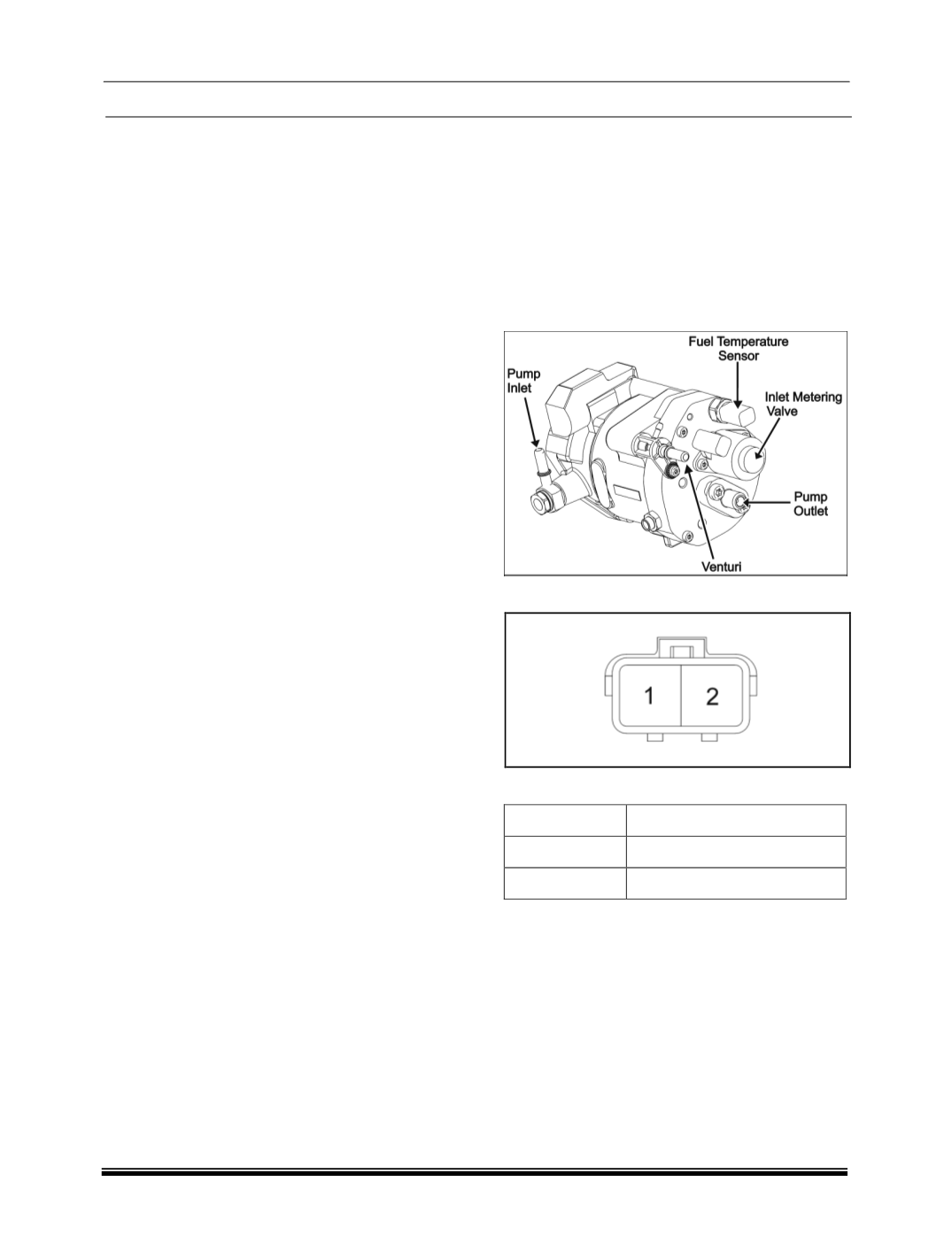
6. FUEL TEMPERATURE SENSOR (
FTS
)
This sensor monitors the temperature of fuel enter-
ing in the HP pump. The fuel temperature sensor
measures fuel temperature on the pump hydraulic
head in the low pressure circuit, between the trans-
fer pump outlet and the inlet to the HP pumping
stage. This sensor information issued to modify rail
pressure control, injection etc. This sensor is in built
with HP Pump.
LOCATION
Connector Details:
PIN OUT DETAIL:
PIN NO
DESCRIPTION
1
Fuel temperature signal
2
Fuel temperature return
INSPECTION:
1. Measure the resistance between the two Fuel
temperature sensor connector terminals; it should
be ~1814.2 ohms at 30 degrees (Consider 30 deg
as room temperature).