


 789 / 1863

GEAR BOX 6450
21
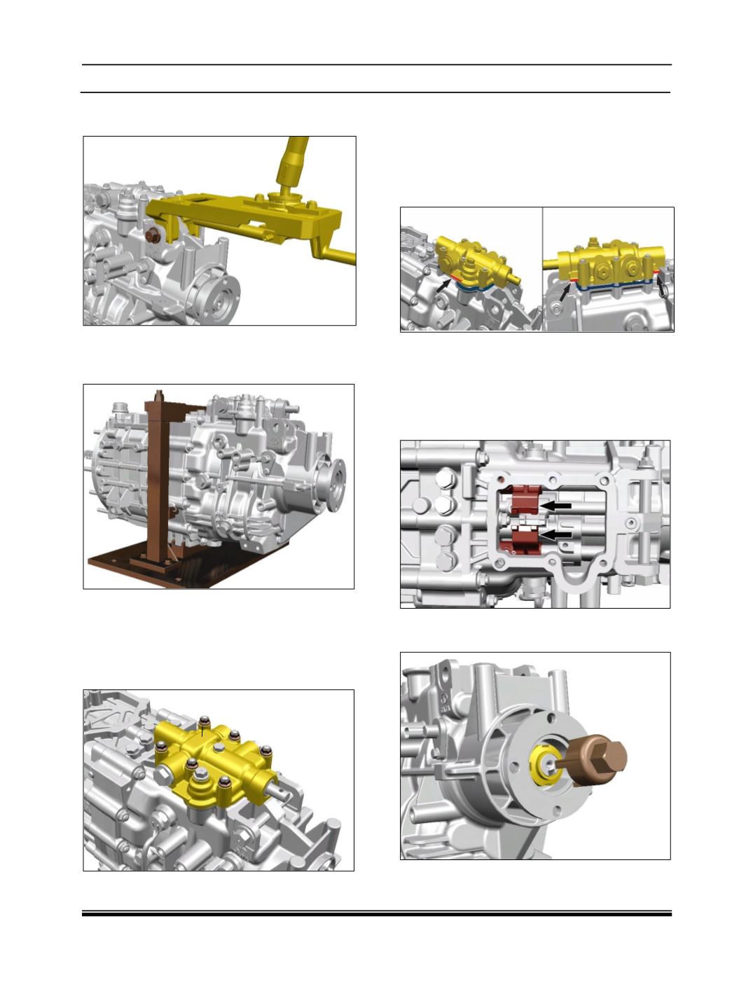
7. Disassemble the extension arm by removing
the extension arm-mounting pin.
8. Mount the gearbox assembly on holding
mounting bracket (Part number: 5403 5890 26
12).
CAUTION:
Make sure gearbox is in neutral position before
starting the disassembly.
9. Loosen and remove nuts (6 nos.) of top cover
assembly.
10. Remove the gasket between top cover and
rear half housing.
CAUTION:
Remove top cover assembly with proper tool at
shown location that can avoid the damage to the
gearbox and top cover assembly surface.
NOTE:
Before removing the coupling flange of gear box
make sure double locking is done (reverse gear
and second gear need to be engage by pushing
dogs forward as shown in figure) for locking of
main shaft.
11. Remove the flange nut by using tool (Part
Number: 2698 5890 41 01).