


 1379 / 1863

ELECTRICAL
77
NOTE
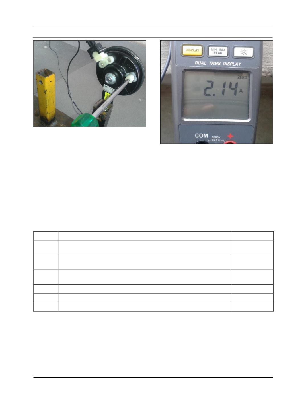
Ensure that the tuning Screw is rotated in the right
direction as indicated near by the Screw. Direction
of rotation is must to tune the Horn in right
direction.
h) Blow the Horn and check Current values.
Normal operating current of OK Horn is 1.8 A
to 3 A.
NOTE
A good Horn will draw around 1.8A to 3.0A current
during operation.
i) If after the above procedure, Tuning kit LED is
not glowing, there is some internal fault in the
Horn and it cannot be adjusted.
HORN REPLACEMENT
If the horn is not working, then declare the Horn as
not working. Replace the Horn as per warranty
policy.
Mandatory Points to be attached along with PCR copy
In case of Horn is replaced under warranty, then following information has to be attached with PCR copy
failing which Horn will be returned to same dealer and no claim will be settled.
Sr. No.
Details to be filled in the PCR copy
Actual Values
1
Horn terminal Voltage measured on Vehicle – As received Condition –
Refer Step-1 of flow chart
----- V DC
2
Wiring harness, Horn Pad, Ground Connection check results – As per Step-
1 to 3, Observation-2 and 3
3
Horn tuning screw adjusted or not – Step-6. LED glowing or not? Tick
appropriate
LED Glows / Not
Glows
4
Horn tuning screw adjusted or not – Step-6. Current Consumed by Horn
----- A DC
5
Current drawn by the replaced Horn (New Horn)
----- A DC
6
Input Voltage measured on Horn terminals (New Horn)
----- V DC