


 584 / 1236

Rear Axle
16
TABLE B
Old
Pinion
Marking
(English)
New Pinion Marking(English)
-10
-8
-5
-3
0
+3
+5
+8
+10
+10
+.20
+.18
+.15
+.13
+.10
+.07
+.05
+.02
0
+8
+.18
+.16
+.13
+.11
+.08
+.05
+.03
0
-.02
+5
+.15
+.13
+.10
+.08
+.05
+.02
0
-.03
-.05
+3
+.13
+.11
+.08
+.06
+.03
0
-.02
-.05
-.07
0
+.10
+.08
+.05
+.03
0
-.03
-.05
-.08
-10
-3
+.07
+.05
+.02
0
-.03
-.06
-.08
-11
-.13
-5
+.05
+.03
0
-.02
-.05
-.08
-10
-.13
-.15
-8
+.02
0
-.03
-.05
-.08
-11
-.13
-.16
-.18
-10
0
-.02
-.05
-.07
-10
-.13
-.15
-.18
-.20
3.6 ESTABLISHING PINION & GEAR DEPTH
USING SERVICE TOOLS & GUAGES
Pinion Position Shim Selection:
Pinion position shim selection can also be done
using a special tool, in the absence of removed
ring/pinion gear.
Install pinion height set master block over pinion
inner bearing cup seat.
Set the dial gauge to 0 (zero), on surface plate.
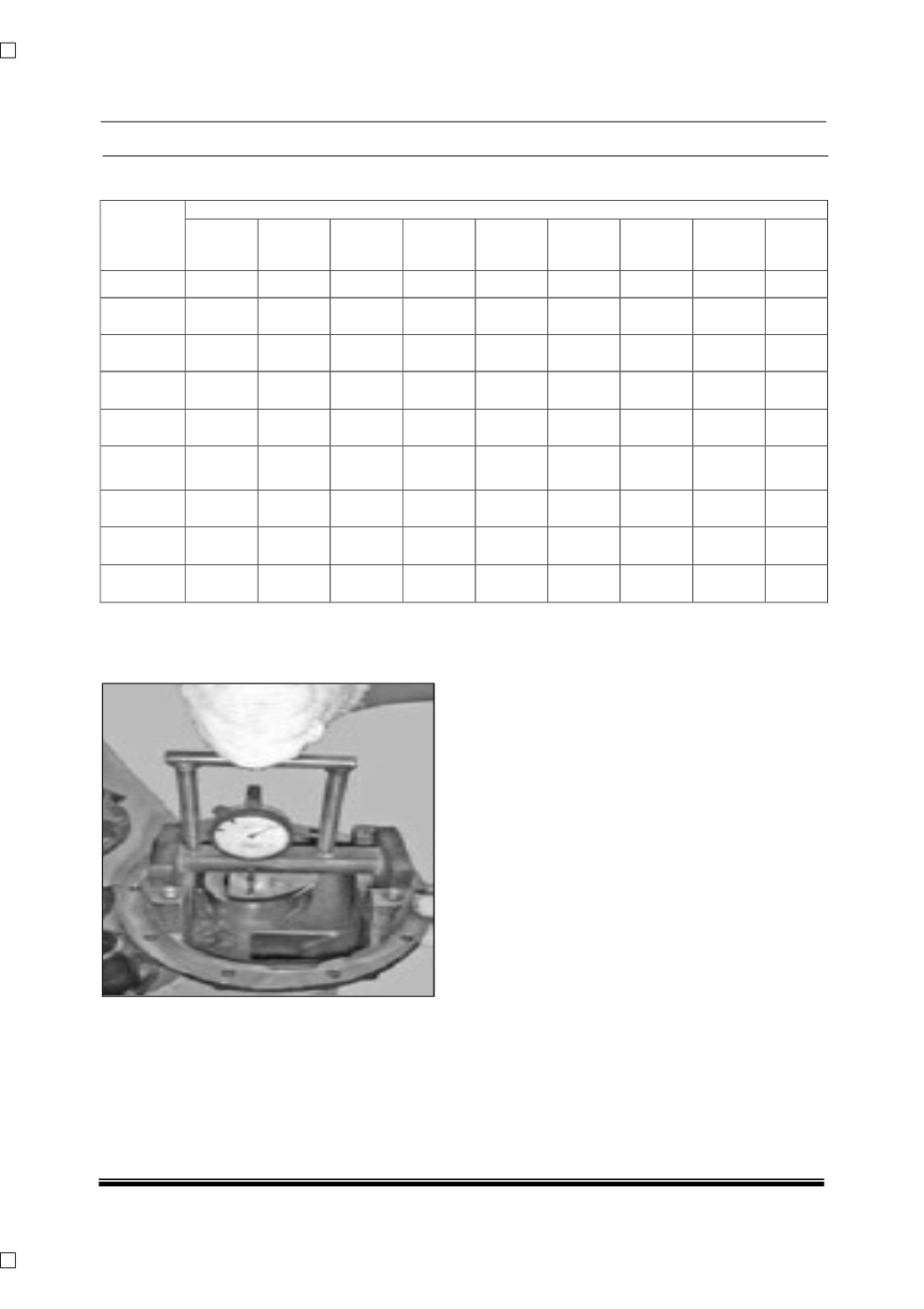
Install dial gauge on pinion height gauge which is
again a part of tool.
Install pinion height set gauge with dial gauge on
side bearing seats. Ensure that plunger of dial
gauge touches top face of pinion height set
master.
Rock depth gauge.
Record maximum reading on gauge needle. Let it
be X'
To calculate shim thickness procedure as follows:
Shim thickness required = X - etched value on
pinion (when etched POSITIVE)
Shim thickness required = X + etched value on
pinion (when etched NEGATIVE)