


 582 / 1236

Rear Axle
14
Remove inner pinion bearing using tools given
below:
Press Adapter, rear pinion bearing cone.
INSPECTION
Inspect gear teeth of side gears and pinion mate
gears for wear and cracks.
Inspect external teeth of side gears for wear &
cracks.
Note:
If replacement of one gear is required, then BOTH
side gears, pinion mate gears and washers have
to be replaced.
Inspect cross pin for excessive wear. Replace if
necessary.
Note:
Always replace gears as a complete set. Do not
mix new gears with old gears, as this may cause
uneven wear and short gear life.
3.0 CARRIER SECTION: [B- CARRIER
RESASSEMBLY]
3.5 RING GEAR & PINION ASSEMBLY
THEORY:
Ring gear and pinion is supplied as a set. They
are matched with each other during manufacture.
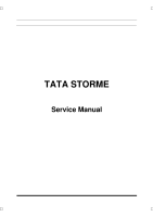
Matching numbers on both pinion and ring gear
are etched for verification.
If a new gear set is used, verify numbers on pinion
and ring for matching before proceeding with
assembly.
Shows ring and pinion etched with inch
Identification. Refer Table A.
Example 1
In metric
In inches
No punched on
removed pinion
+ 8 m
+3
No punch on new
pinion
-5 m
-2
Value derived from
table
+0.13
+0.005
Thickness of shims
in OE assembly
x
y
Thickness of shims
in selected for new
ring/pinion
X + 0.13
Y + 0.005
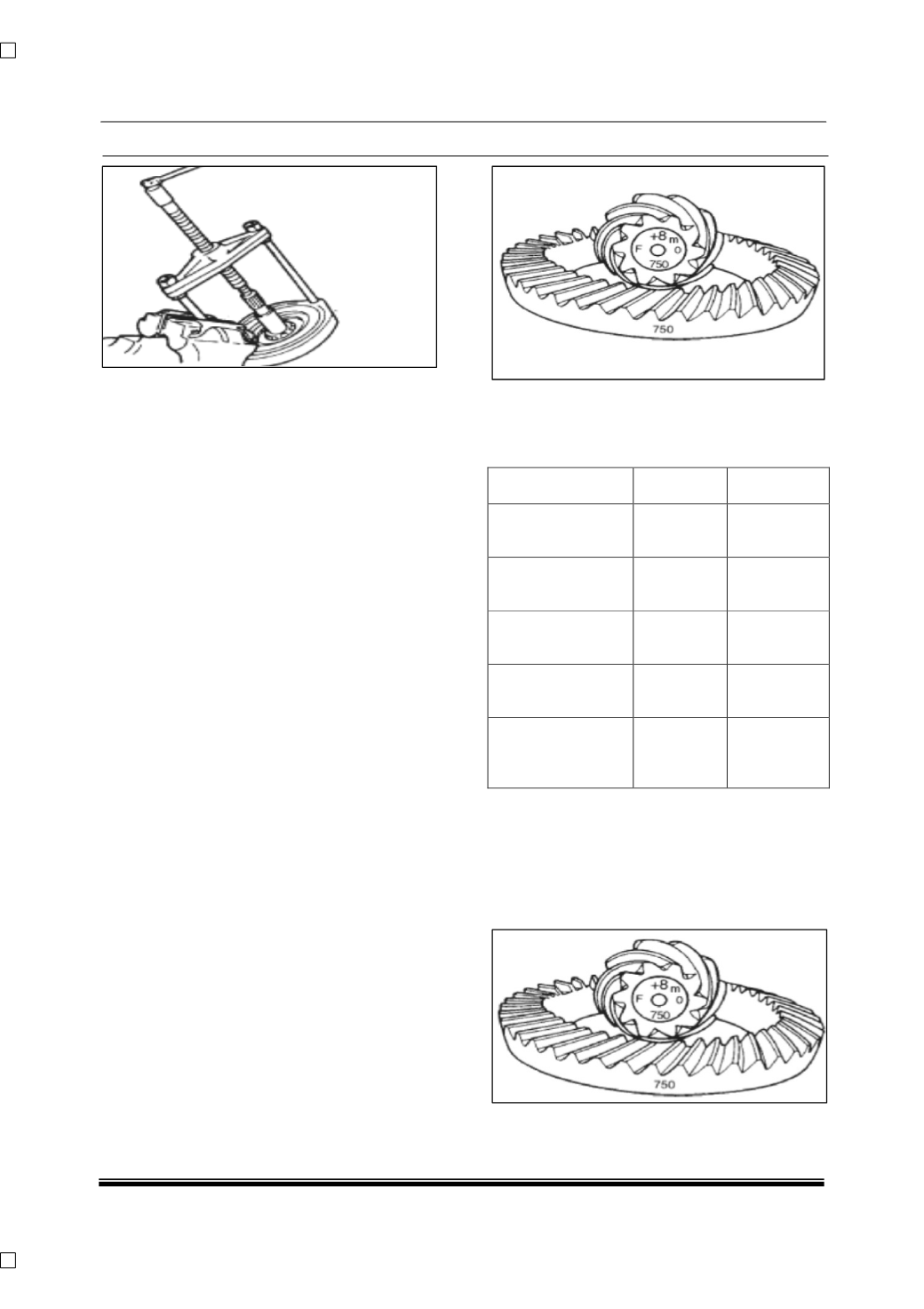
Standard mounting distance from center line of
ring gear to back face of pinion is 103.5 ± 0.1 mm.
This dimension is controlled by selecting shims,
which are positioned between the inner pinion
bearing cone and pinion gear. Best running
position of gear set is achieved by proper shim
selection.