


 966 / 1526

110
ENGINE2.2LDICOR
EGRpipe
This pipe connects the exhaust manifold to the EGR
valve. Through this pipe Exhaust gas is routed to the
intake manifold and mixes with the fresh air.
ECU
The EGR system of the vehicle is controlled more
precisely based on environmental conditions such as
atmospheric pressure, air temperature, engine
conditions (engine speed, pedal position, coolant
temperature etc).The ECU is mounted inside the
engine compartment.
NOTE
l
Ensure that exhaust systemand catalytic converter
are not blocked and are free from obstruction.
l
Blockages in the exhaust can create back pressure,
low top speed, poor pick up, black smoke, carbon
build up and low mileage.
l
Check and ensure EGRValve &Control System is
Clean and functioning properly.
l
Damaged or pinched vacuum lines / wrong
connections of vacuum pipes.
l
EGR-EVRV, Turbocharger-EVRV aresame. Ensure
that correct connections can made on both of
these EVRVs. Interchanging these connection can
keep the 'EGR' open when not desired and vice
versa. Either way these can seriously affect power
output of the engine and also the emission levels.
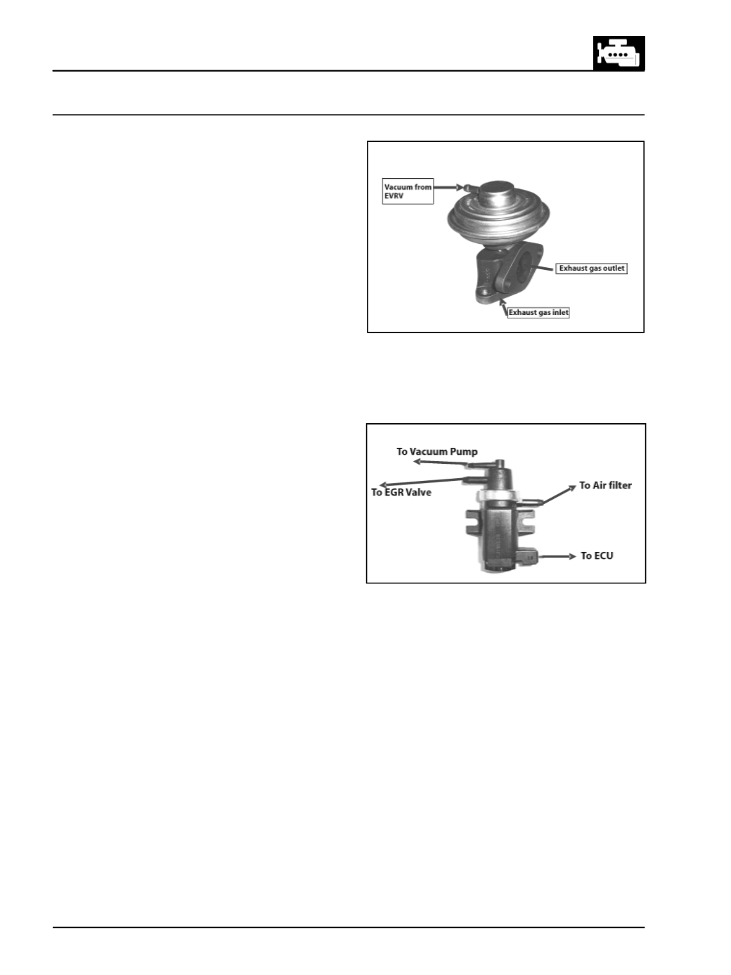
Electronic VacuumRegulating Valve (EVRV)
(Fig.
225)
The EVRV is an electro pneumatic solenoid switch,
which is controlled more precisely by the ECU, based
on the Engine speed, Coolant Temperature and
Accelerator pedal position etc. EVRV provides variable
vaccum levels to drive EGR&VNT.
NOTE
Care should be taken to connect the ports of the EVRV
to their respective hoses. Any interchanging of the
connections will lead to malfunctioning of the EGR
system.
EGRSYSTEMCOMPONENTS
EGRValve
(Fig. 224)
The EGR valve is a diaphragmvalve that is actuated by
vacuum from the Vacuum Pump through EVRV.The
valve is fitted to EGR cooler which is mounted on the
inlet manifold. It has three connections, one for the
vacuum, one for the exhaust gas inlet from the exhaust
manifold and one for the exhaust gas outlet to the
inlet manifold. The exhaust gas starts flowing into the
inlet manifold once the vacuum is fed into the valve.
Fig. 224
Fig. 225